
3 Dimensional Realtime VR Software Package, which support
the consensus building in road and public construction projects
International Version (Japanese, English, Chinese,
Korean, Italian, German, French)
UC-win/Road Ver.19
Initial Release:2000.05.09 / Latest Ver.:2026.05.29
- Ultimate
- USD19,200
- Driving Sim
- USD12,800
- Advanced
- USD9,700
- Standard
- USD6,300
- CIM Lite
- USD5,280
- Multi User Client Version
- USD1,180
- Presentation Version
- USD660
- Cluster Client Version
- USD660
- Free Viewer Version
- Free
Program Overview >> New Functions of Ver.19 NEW!
3D real-time virtual reality software UC-win/Road won the 2002 Software Product of the Year.
It is advanced software that enables the creation of large scale 3D spaces for all sorts of projects by simple PC operations and with which you can give a variety of presentations in real-time.
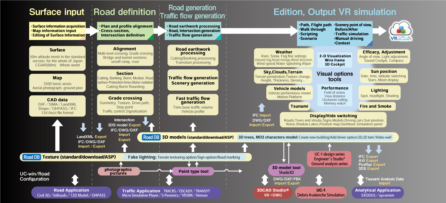

"F8-AI® UC Support"
AI-driven chat supports your design work
Supports UC Support AI and Design Support AI, enabling users to ask operation questions and give work instructions in natural language.
Users can generate and update VR models by entering prompts via the MCP server (AI agent).
"Design Support AI" is supported in all program versions with editing functions, including CIM Light, Standard, Advanced, Drive Sim, and Ultimate.
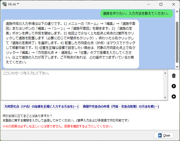
Standard / CAD Data Utilization
-
- 50m topographic mesh of New Zealand
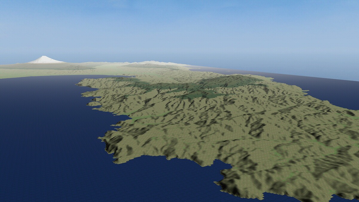
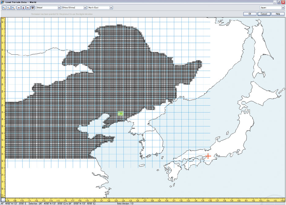
- "CGIAR-CSI SRTM 90m Database" for all parts of the world geographical features of China and Australia
- SRTM(90m mesh), ASTER(30m mesh)
- BlueMarbleNextGeneration(500m mesh)(Support the topography of the seabed)
- World geographic coordinate system conversion tool authorization: (#603, Planning and Coordination Division of the Geographical Survey Institute)
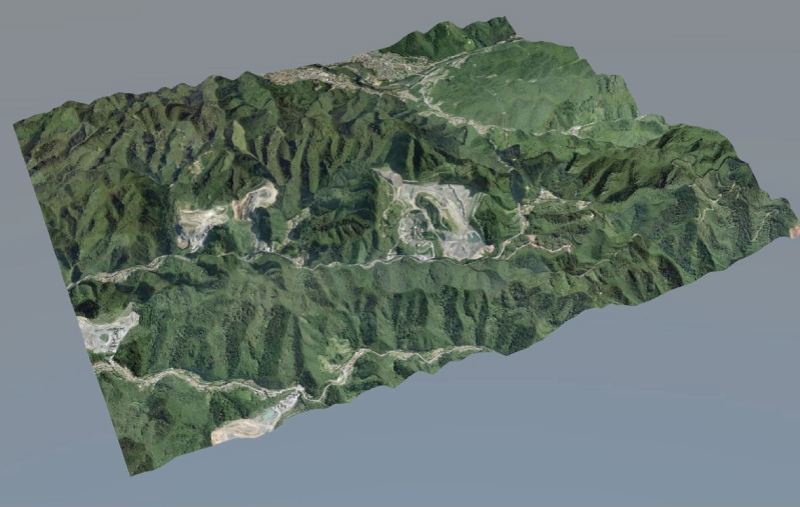
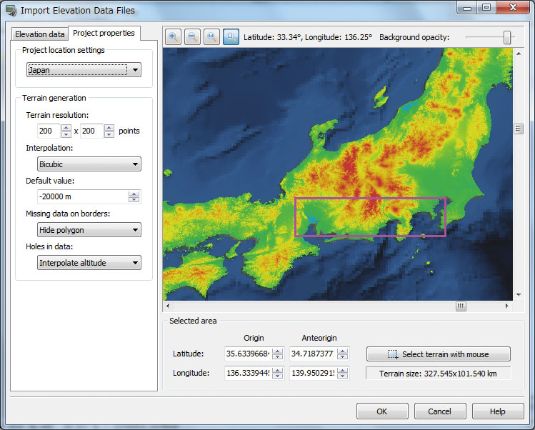
- Highly accurate terrain can be created whilst specifying its resolution.
●Terrain data and map are included on the database.
●Arbitrary terrain and world geographic coordinate system conversion.
●Paste of satellite photo, DXF-XML conversion, 3D and 2D terrain editing
●3D and 2D data exchange with CAD by Shape, IFC, and DWG
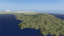
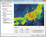
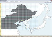
Digital map of geospatial information authority of Japan
50m mesh elevation (nationwide) (2000, #173). 5m mesh elevation, import of GSI tiles
Geographical features of the world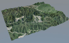
●PLATEAU data import
Road, building and bridge data can be imported from PLATEAU, a project initiated by the Ministry of Land, Infrastructure, Transport and Tourism to develop, utilize, and make open data 3D city models across Japan. It can also be used with GIS data such as Shape files and point cloud data supported by UC-win/Road.
By overlaying various information on infrastructure development plans and urban activities on this base data, it can be used for urban planning, simulation and analysis. The system also supports CityGML, which defines all kinds of attribute information on buildings, structures, etc.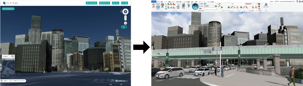
Left: PLATEAU (Nihonbashi, Toky)
Right: PLATEAU data imported in UC-win/Road
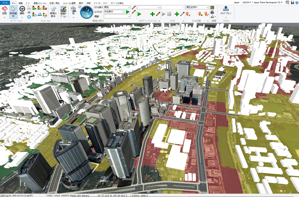
PLATEAU data utilized in UC-win/Road 3D Hazard Map
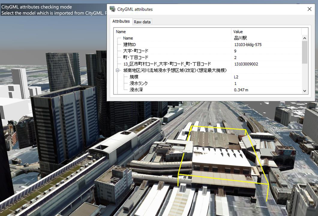
Import CityGML models to check the attribute
of Shinagawa Station (Terrain and aerial photos published
by Geospatial Information Authority of Japan)●CityGML data export
UC-win/Road is used as a platform to create, edit and output city models from UC-win/Road. UC-win/Road can output LOD1-2 building models and LOD1 road and terrain models, etc. When PLATEAU's CityGML is loaded, the CityGML data can be re-exported with the same information as the CityGML data, so that the original information can be reproduced and output as much as possible except for the parts that have been changed.

●Import of Flood Navi Data
The Tsunami Plug-in is now equipped with a function to download inundation data from the Flood Navi system of the Ministry of Land, Infrastructure, Transport and Tourism, enabling visual inundation simulations using the data on UC-win/Road. It is possible to check water level changes over time and visualize gradients to create a realistic representation of the water surface by using the Tsunami Plug-in function.
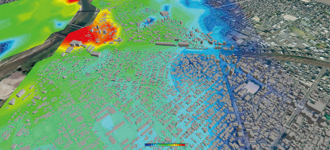
Simulation on UC-win/Road using Flood Navi data
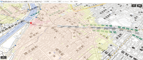
Animation on the MLIT's Flood Navi
Efficient VR data creation assistance through the use of standard models/textures and an extensive download DB
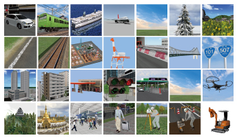
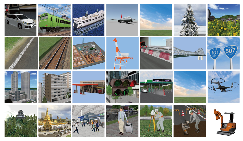
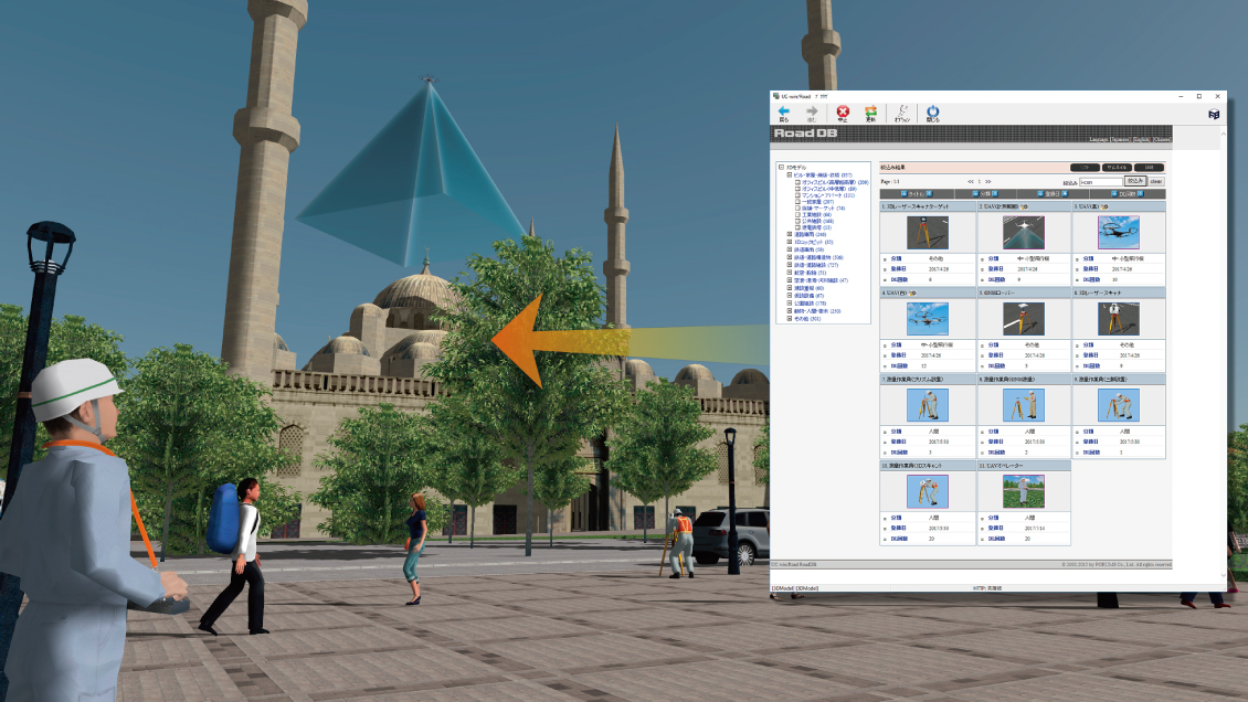
In addition to the standard data including 3D models and textures, extensive downloads are available directly from the UC-win/RoadDB on the Internet. Useful editing and movement tools are available, allowing scaling up and down, movement, rotation, inclination and arrangement of models. Action setting offers generation and motion control of moving models. Signs, stairs, escalators, and fences can be created by using parametric entering.



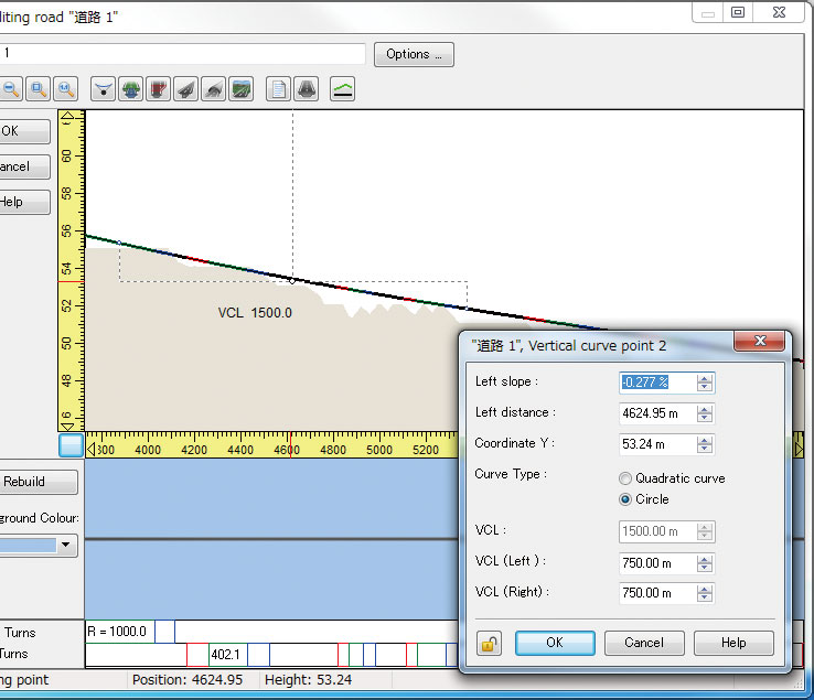
Easy creation of a complicated road structure is available with high definition.
-
All sorts of lines such as roads, rivers, lakes or flight paths can be set up with parameters or free hand drawing and roads, tunnels, bridges, rivers or walking routes can be automatically created.
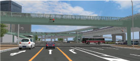
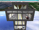
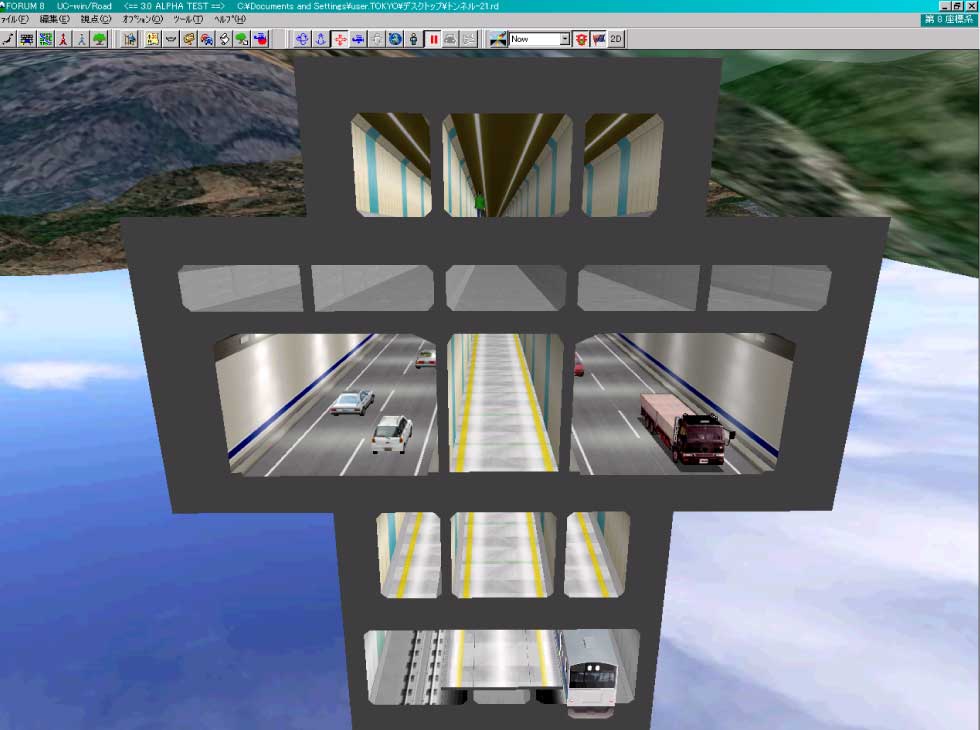
Tunnel and bridge sections are set by the definition of a horizontal road alignment (clothoid and spline supported) and a vertical alignment. Texture process and cutting and banking process considering small steps are conducted in the section definition. Complicated road structures can be created easily by the linear and section functions.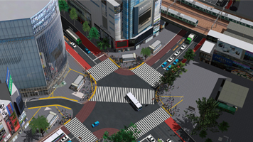
Traffic flow creation
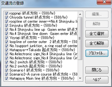
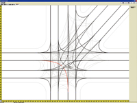
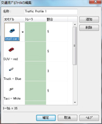
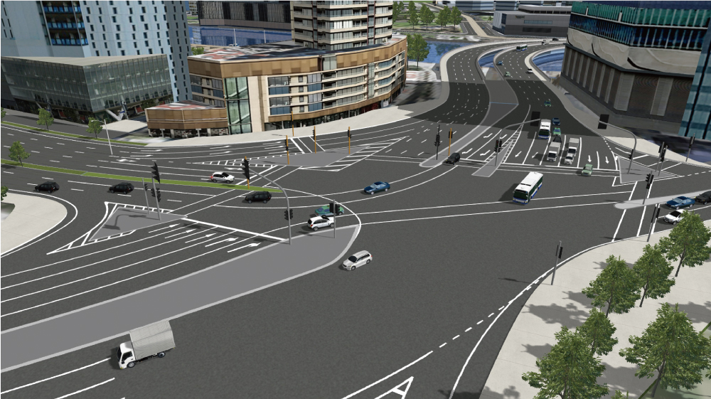
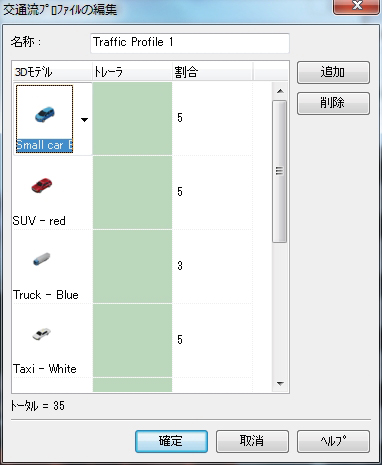
Traffic flow creation by traffic volume setting and ratio of Traffic Generators / Flow by vehicle type. Control of collision
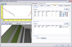
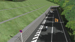
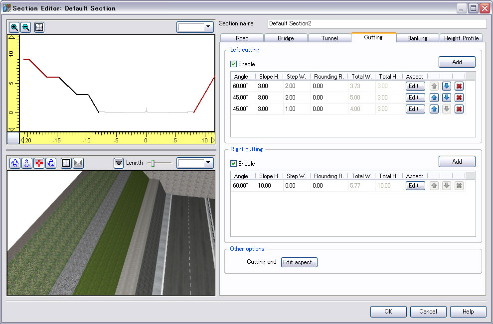
Improved cuttings and banks and rounding of a small stage
We have improved the setting method of cuttings and banks. It allows the setting of width, angle of slope and textures for each stage of the right side and the left side. The rounding can be set for the berm.






Various Data Integration
-
IFC, Shape, LandXML, and DWG. Other data cooperation expands the engineering world infinitely.
Survey
●Integration with terrain data
・Input/Output point cloud data -> Create terrain
・Input/Output IFC data
・LandXML Import
・Shapefile
・UAV plug-in
・12d Model plug-in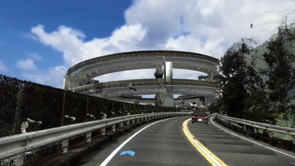
▲Point cloud plug-in
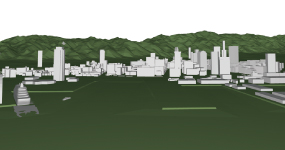
▲IFC plug-in
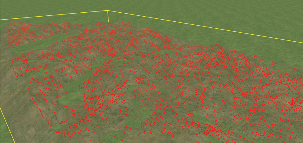
▲LandXML import
Outline Design / Detailed Design
●Data integration with UC-1 Design Series
●Data integration with Road CAD
・IFC data input/output
・LandXML import
・DWG plug-in●Data integration with 3D CAD
・Shade3D
・Allplan
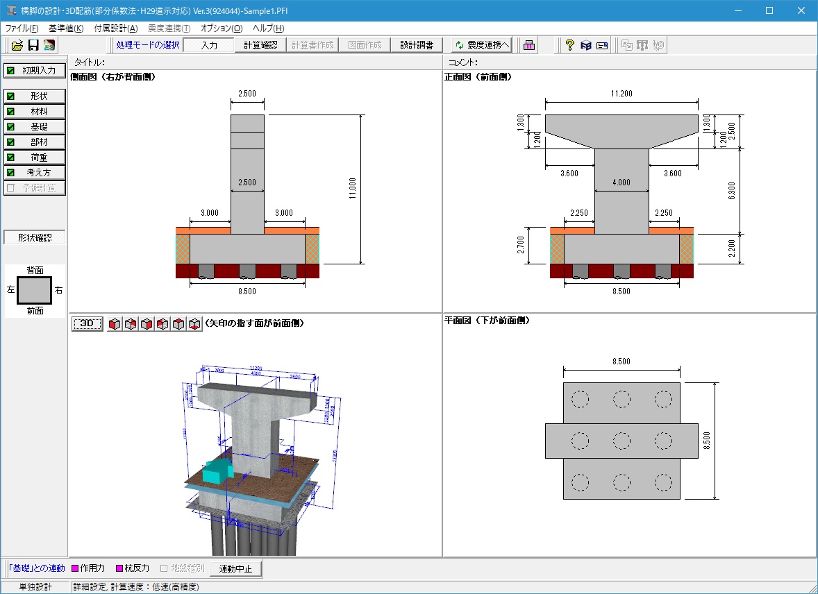
▲UC-1 series
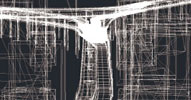
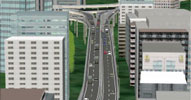
▲DWG export result / UC-win/Road
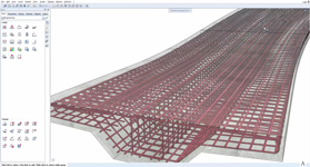
▲Allplan
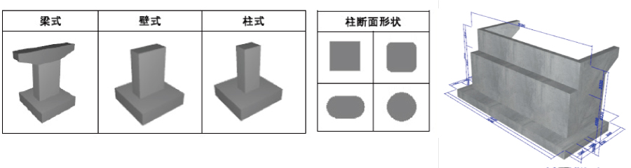
▲3D Parametric Tool
Simulation / Design Check
●Data integration with UC-1 Design Series
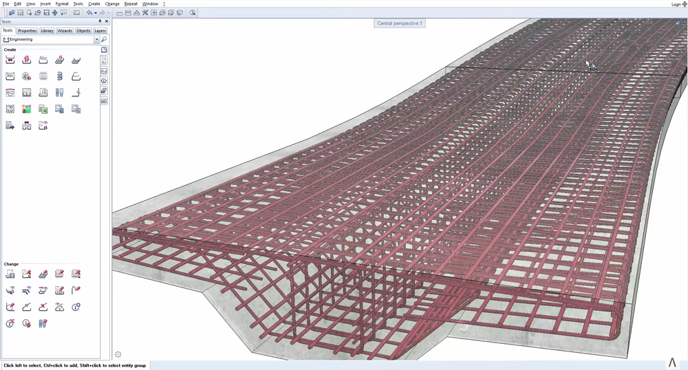
・3D bar arrangement CAD
・3DCAD Studio®●Data integration with analysis software
・Engineer’s Studio®
・Debris Flow Simulation
・EXODUS plug-in
・xpswmm plug-in●Data integration with traffic AP
・OSCADY PRO
・TRANSYT
・Aimsun
・VISSIM
・S-PARAMICS
・TRACKS
・SIDRA●Design check
・Shade3D
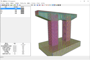
▲3D bar arrangement CAD

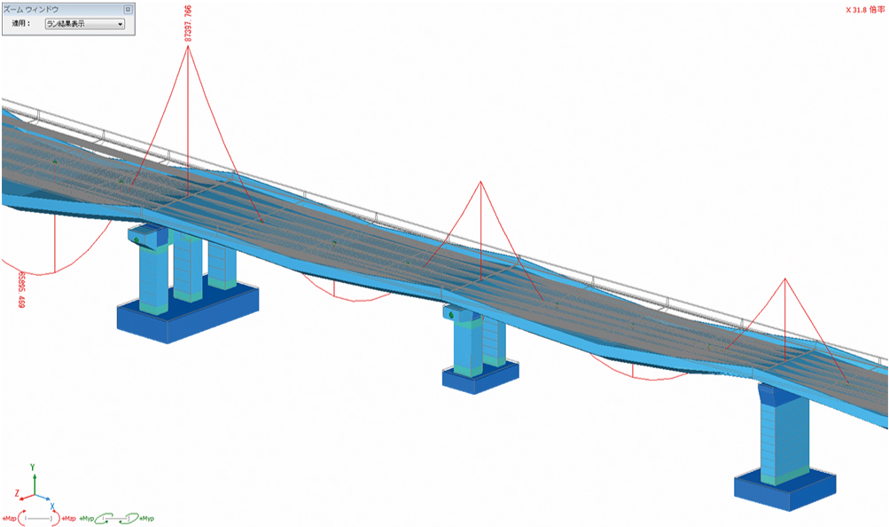
▲FEM analysis

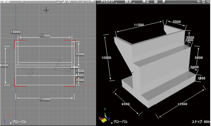
▲BIM/CIM Design Check Tool
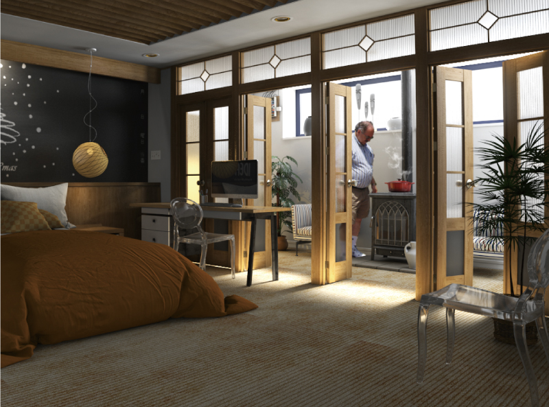
▲CG rendering
Construction
●Construction Simulation
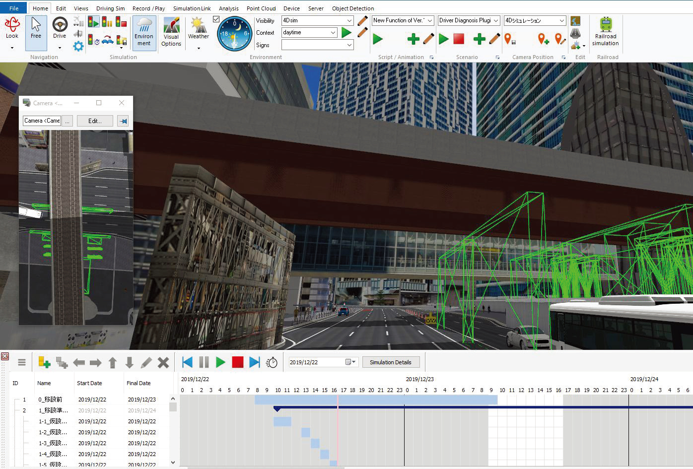
・4D simulation
・Soil calculation
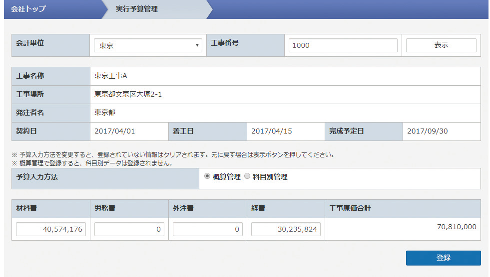
・Quantity calculation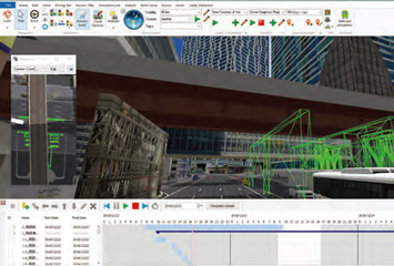
▲4D simulation
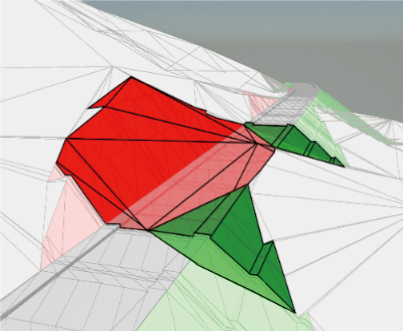
▲Soil calculation
 Suite Addition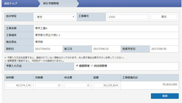
▲Quantity calculation linked with Suite Addition
Maintenance
●Digital Twin
●Inspection
・UAV plug-in

▲UAV plug-in


Large-scale VR support
-
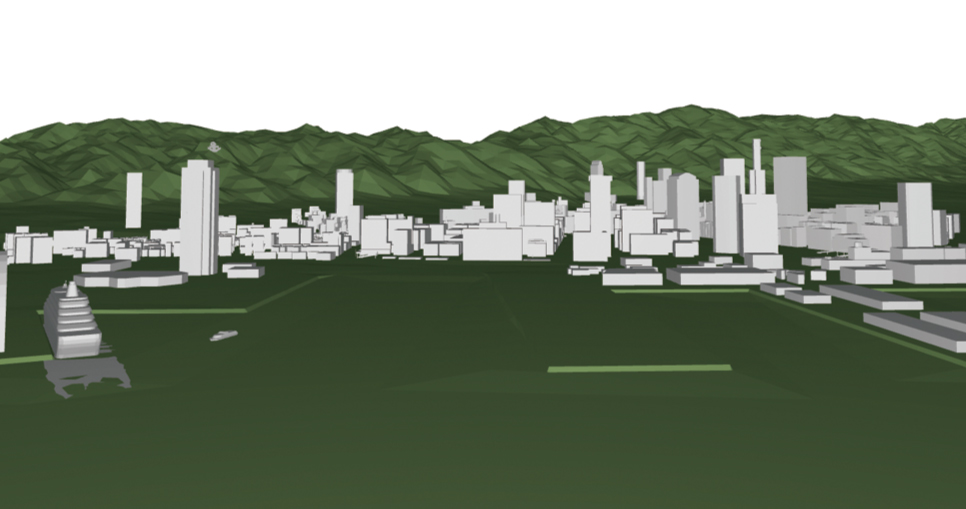
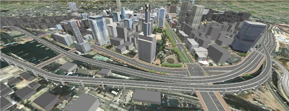
64bit native support. It's possible to create data from the size of a dice to several hundred kilometer road structure in the same space.
Dynamic display of LOD and the smooth processing of vast terrain and many fine models.
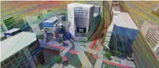
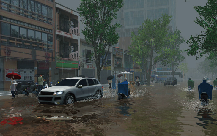
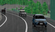
Various displays with the Visual Options Tool. Traffic simulation of road hazards are also available.
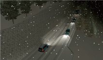
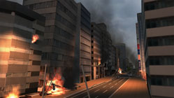
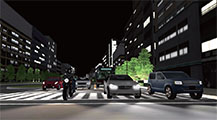
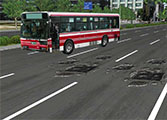
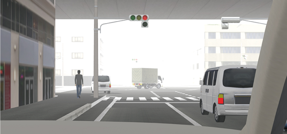
Also available are real-time control of time,weather, and lighting. You can display day and night scenes with a range of lighting conditions using the artificial light feature. Generating traffic streams based on traffic volume, vehicle profiles, traffic light configurations, as well as simulating traffic obstructions, disasters and accidents can also be carried out.
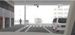
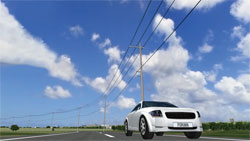

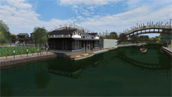
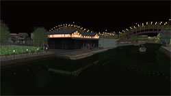
Real-time VR operation by simple operations. A variety of functions helping presenters
Driving simulations
UC-win/Road supports several driving modes (speed of car, lane changing, height of viewpoint, viewpoint switching in 8 directions) and dynamic movement of viewpoint (from other cars, up and down, turn head). Automatic flight and walk-throughs are available with the flight path setting (editing in the 3D display is supported). More advanced simulation can be performed with manual driving and support for a 3D cockpit and multi-monitors.
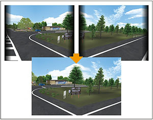
Camera position switching by Before/After
Before, After, and user specified display of model, sign, and tree up to 20 patterns.

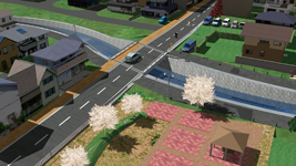
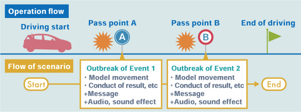
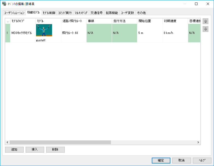
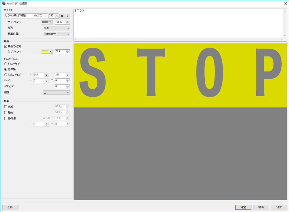
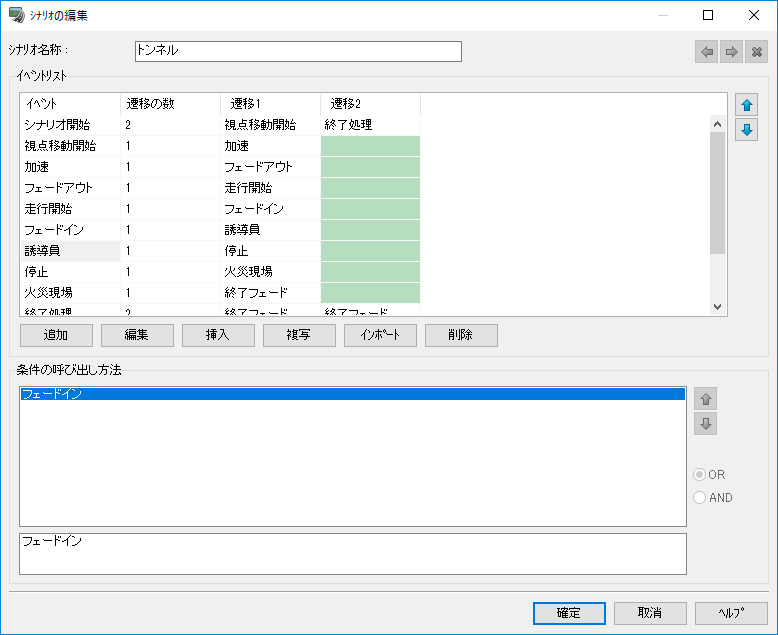
Scenario
Set various moves to models and simulate scenarios with possible events and conditions to be tested makes viewers to understand the meaning of VR creation.

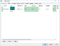
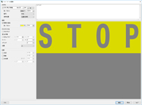
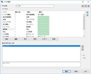
Easy and detailed setting
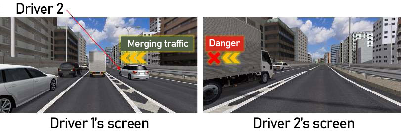
Multi-user Scenario
Cooperating with the existing multi-user cluster function, it is possible to change scenario transition conditions according to the status of client users. Also, events can be issued to not only main users but also client users.




TOPICS
UC-win/Road TOPICS
-
-

● Won the Special award of the 8th CSAJ Alliance Award! (Japanese)
Awarded product:UC-win/Road for SaaS (Current name: VR-Cloud®)
This award is organized by Computer Software Association of Japan. https://www.saj.or.jp/english/index.html
The judgement is performed based on the actual achievement and potential of affiliation, the number of business,
future possibilities, marketability, and technology.● Awarded with "Outstanding Technology Award" at the Construction
Technology Expo, Kinki, 2003!
● SOFTWARE PRODUCT OF THE YEAR 2002! Awarded in "Social/life category"
This award is given by Software Information Center (SOFTIC)http://www.softic.or.jp to excellent software products.
UC-win/Road Ver.14 passed a OCF test for software supporting 3D design data based on LandXML.
On Nov. 29, 2019, UC-win/Road Ver.14 passed a OCF test for software supporting 3D design data based on LandXML.
(OCF: http://www.ocf.or.jp/)
UC-win/Road Ver.12 acquired PSQ certification
On June 28, 2017, FORUM8 acquired "Approval" certification based on the PSQ certificate system for UC-win/Road Ver.12.1.
Press Release - FORUM8 acquired PSQ certification for UC-win/Road Ver.12 (Japanese)
-Ensures high reliability on the basis of system development, expands demands of system development
customization for public offices- (2017/07/07)
- FORUM8 acquired PSQ certification for UC-win/Road Ver.12 (Japanese)
UC-win/Road TOPICS
-
Related Information
-
- ◆Press Release
- FORUM8 has released VR Design Studio UC-win/Road Ver.14.('19 November 20th)
- FORUM8 released UC-win/Road Ver.12 and acquired patents related to VR and DS. ('17 July 7, in Japanese)
- ◆Related Product
- UC-win/Road Support System
- 3D・VR Engineering Service
- ◆New Product Information
- UC-win/Road Ver.15 (Up&Coming '21 New Year issue)
- UC-win/Road Ver.15 (Up&Coming '20 Fall issue)
- UC-win/Road Ver.14.2 (Up&Coming '20 Summer issue)
- UC-win/Road Ver.14.1 4D Simulation Plug-in (Up&Coming '20 Spring issue)
- UC-win/Road Ver.14 (Up&Coming 2019 Spring issue)
- UC-win/Road Ver.14 4D simulation (Up&Coming 2018 Fall issue)
- ◆Up&Coming series
- Support Topics
- ◆Seminar & Event Report
- The 17th 3D VR Simulation Contest on Cloud (Up&Coming '19 New Year issue)
- ◆Video Gallery / Contest
- Video Gallery of Examples of Practical Use of UC-win/Road
- The 18th 3D VR Simulation Contest Review
- ◆Keynote Speech / Presentation Papers
- Conference about BIM at Pisa University in Italy
UC-win/Road Ver.6 is available in Italian.
"BUILDING INFORMATION MODELING(PDF, 219KB)" ('17.02.24) - ◆Seminar
- UC-win/Road VR seminar
Related Information
UC-win/Road Ver.19 New Features
●UC Support AI and Design Support AI
Users can ask operation questions and give work instructions in natural language, as well as generate and update VR models by entering prompts via the MCP server (AI agent).
"Design Support AI" is supported in all program versions with editing functions, including CIM Light, Standard, Advanced, Drive Sim, and Ultimate.
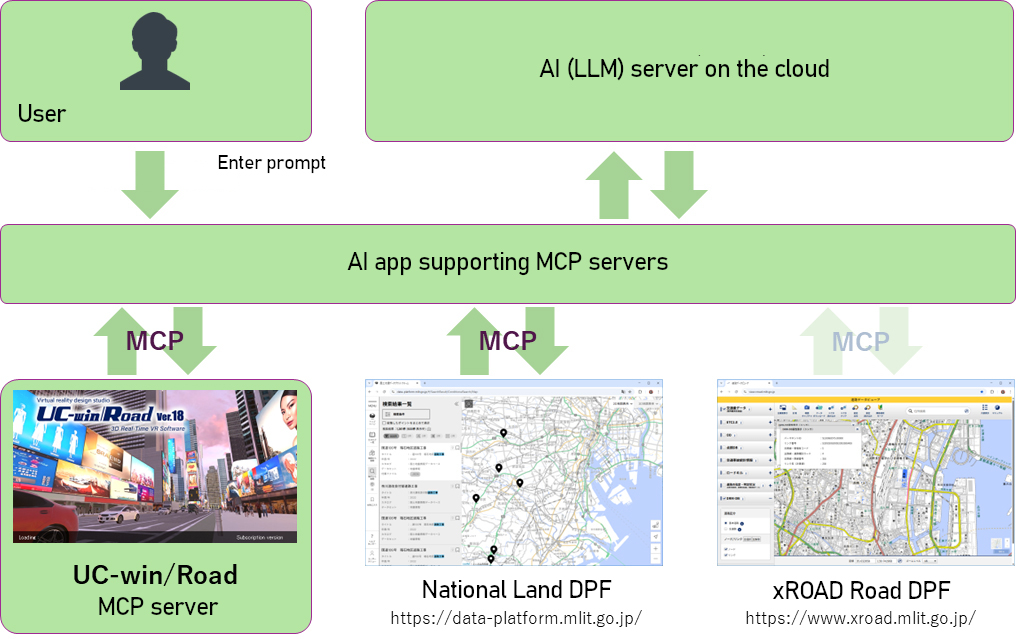
UC-win/Road MCP support and concept of integration with other systems
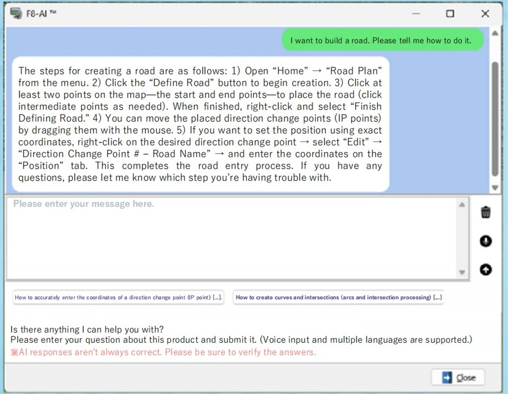
F8-AI® Support
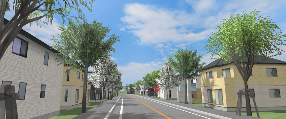
Example of 3D spatial data creation using AI-driven processing
●Road creation and editing on a 3D display
Users can place roads and edit their shapes directly on a 3D display, enabling intuitive road model creation based on point cloud data and city models.
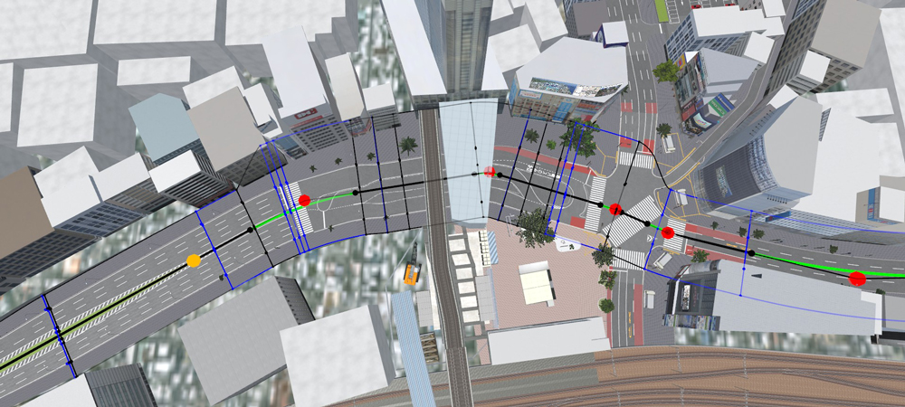
Road editing screen
Integration with point clouds and 3D models, and practical use examples
Users can intuitively create and refine accurate road models based on measured data by editing road shapes directly on a 3D display with point clouds overlaid. Vertical profiles and sectional relationships can be checked and adjusted in real time by overlaying them on point clouds.
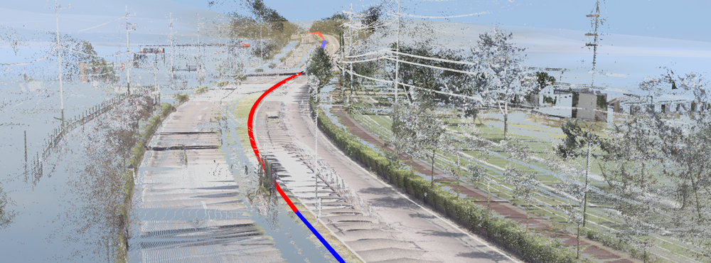
Definition of planar alignment in 3D space
Users can adjust sidewalk widths and curb positions in urban areas and instantly check their fit with surrounding buildings and trees in a 3D view. Section changes—such as lane count adjustments near intersections or adding a right‑turn lane—can be reviewed seamlessly while editing sections and transitions on a 3D display. A fully 3D‑based feedback loop enhances both the quality and speed of design.
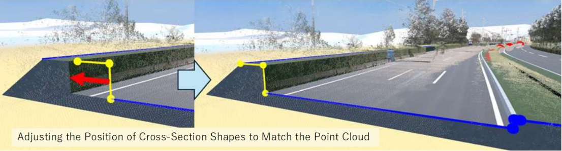
Examples of road alignment definition and cross-section editing
●Passthrough display support for VR devices
To support new features in VR devices, the integration method has been updated to the open standard OpenXR. Previously, the Quest Rift plugin supported only head‑mounted displays such as Meta’s Quest series. With the addition of OpenXR support, the system can now integrate with a wider range of SteamVR‑compatible devices, including products like the HTC VIVE series.
●Integration with the National Land and Traffic Data Platform (Road Traffic Census data)
By importing real traffic volume data, it is possible to build a traffic simulation environment that reflects actual road conditions.
●Other feature improvements
- Enhanced ramp connections: connecting ramps to existing roads, assigning multiple roads to a single ramp, and editing or disconnecting lane connections.
- Road cross‑section mirroring: enabling the mirroring and saving of cross sections, bridges, and tunnels.
- Improved input for road cross-section coordinates and codes: supporting the import of 5-m mesh (DEM5B, DEM5C) and 1-m mesh (DEM1A).
- Update to CityGML import: supporting the PLATEAU standard specification Ver.5.0 (i‑UR 3.2), and enabling the import of urban‑planning feature types.
- J-LandXML export: Supporting the export of standard cross‑section information in the J‑LandXML format.
- FBX animation: adjusting the number of bones used from one to eight to reduce drawing load.
- Material settings panel: allowing the thumbnail display to be selected between sphere view and plane view.
- Improved walking mode: continuing diagonal movement along walls instead of stopping when colliding with them.
- Improved Physically Based Rendering: enhancing compatibility by supporting the mikkTSpace algorithm for glTF normal maps.
- Support for curved road signs: adding a curvature setting to the road‑sign display component to enable curved sign representation.
- 360-degree image generation: supporting Physically Based Rendering in the stereo-image generator.
- Simulink Plugin: adding a synchronization function for user data and user variables to enable controlling scenario events from Simulink.
- Updates to VISSIM support: VISSIM 2025 and VISSIM 2026 can be selected now.
Functions and Features
Plan & Design
-
- The geographical features are enhanced.
- Using the "CGIAR-CSI SRTM 90m Database" for all parts of the world, geographical features of China and Australia are installed in UC-win/Road.
- SRTM(90m mesh), ASTER(30m mesh)
- BlueMarbleNextGeneration(500m mesh)(Support the topography of the seabed)
- Highly accurate terrain can be created whilst specifying its resolution.
- The large terrain exceeding 100km in area can now be generated.
- Import (2D/3D): Road Section, 3D model
- Export: by category (model, line shape, geography), whole
●Digital map of geospatial information authority of Japan
50m mesh (elevation)(Approved number: 2000, #173), Format of 5m/10m mesh (elevation)
●Geographical features of the world
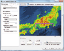
▲ Seafloor topography
●PLATEAU data import
Road, building and bridge data can be imported from PLATEAU, a project initiated by the Ministry of Land, Infrastructure, Transport and Tourism to develop, utilize, and make open data 3D city models across Japan. It can also be used with GIS data such as Shape files and point cloud data supported by UC-win/Road.
By overlaying various information on infrastructure development plans and urban activities on this base data, it can be used for urban planning, simulation and analysis. The system also supports CityGML, which defines all kinds of attribute information on buildings, structures, etc.Left: PLATEAU (Nihonbashi, Toky)
Right: PLATEAU data imported in UC-win/RoadPLATEAU data utilized in UC-win/Road 3D Hazard Map
Import CityGML models to check the attribute
of Shinagawa Station (Terrain and aerial photos published
by Geospatial Information Authority of Japan)●CityGML data export
UC-win/Road is used as a platform to create, edit and output city models from UC-win/Road. UC-win/Road can output LOD1-2 building models and LOD1 road and terrain models, etc. When PLATEAU's CityGML is loaded, the CityGML data can be re-exported with the same information as the CityGML data, so that the original information can be reproduced and output as much as possible except for the parts that have been changed.
●Import of Flood Navi Data
The Tsunami Plug-in is now equipped with a function to download inundation data from the Flood Navi system of the Ministry of Land, Infrastructure, Transport and Tourism, enabling visual inundation simulations using the data on UC-win/Road. It is possible to check water level changes over time and visualize gradients to create a realistic representation of the water surface by using the Tsunami Plug-in function.
Simulation on UC-win/Road using Flood Navi data
Animation on the MLIT's Flood Navi
●OpenDrive Import
ASAM OpenDRIVE® files can be imported. This function reduces costs for creating simulation environments by importing road networks (road, lane) created in external software into UC-win/Road via OpenDRIVE®. The supported version is ASAM OpenDRIVE® Version: 1.7.0.
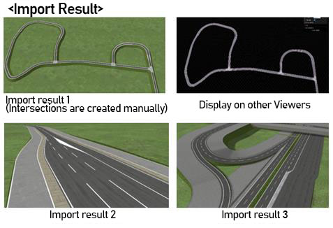
●Curve calculation function
Curve parameter of IP point can be calculated from dot sequence obtained by GPS.
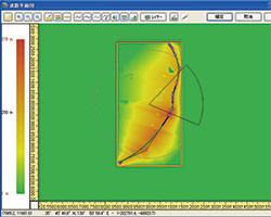
●Road-Terrain matching process
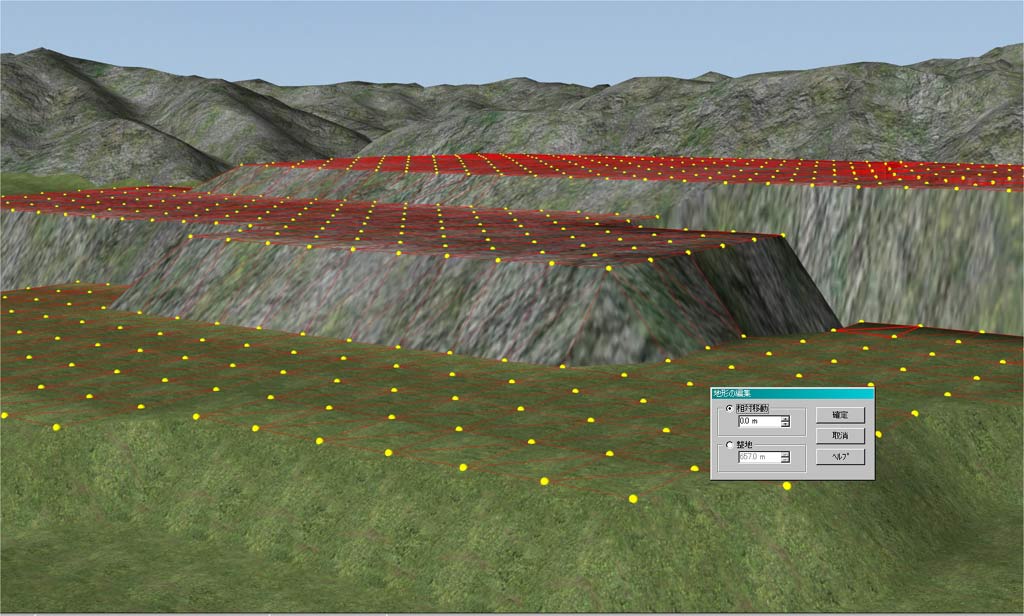
Deal with terrain matching processing in addition to cutting and banking by road generation.
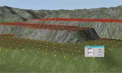
▲ Leveling processing
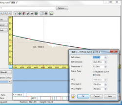
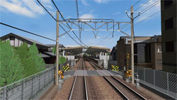
●Vertical curve of railroad
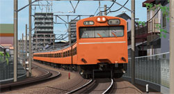
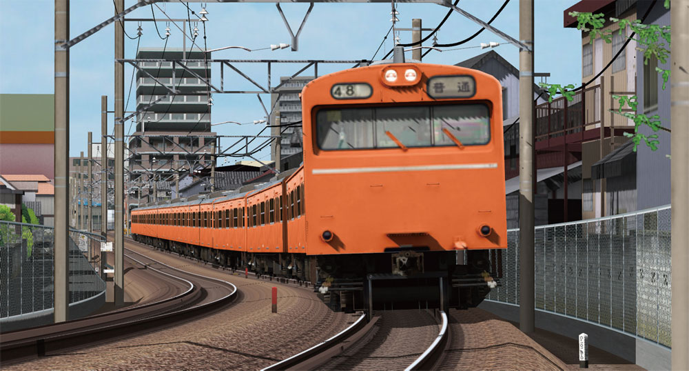
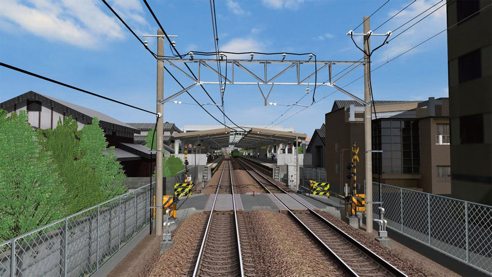
Ability to draw the centerline for railway surveying and the centerline of structure for construction surveying, transition curves and vertical curves, cant of a railway track, railroad switch. Trains can be made to travel over multiple tracks.
Transition Curves: Clothoid, Cubic parabola, Sine half wave length curve
Vertical Curves: Secondary parabola, circular curves
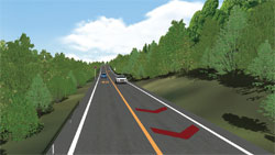
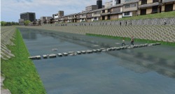
●River, road cross section
Planar and longitudinal alignment is now possible.
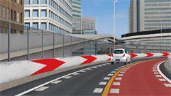
●Transparency of cross sections
Transparency rates of parts are selectable in the cross section editor. Transparency of transparent panels and translucency of a sound insulation wall or balustrade can be expressed easily
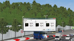
●Improved cuttings and banks and rounding of a small stage
We have improved the setting method of cuttings and banks. It allows the setting of width, angle of slope and textures for each stage of the right side and the left side. The rounding can be set for the berm.
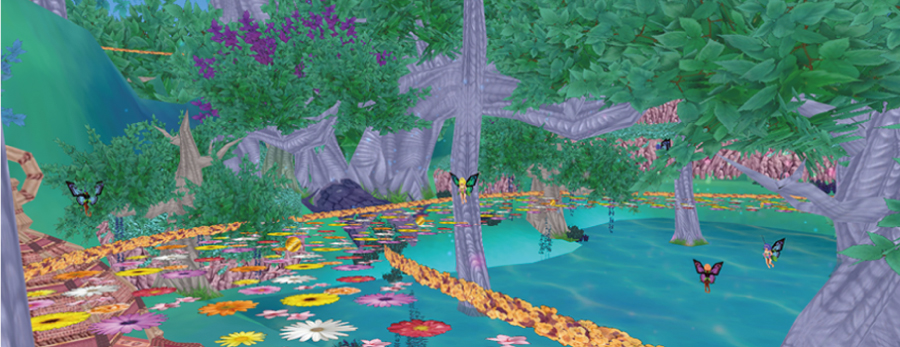
●Generating forests
This feature allows the automatic generation of between several hundred and several thousand trees at predefined locations. Collective deletion is also available.
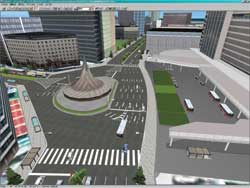
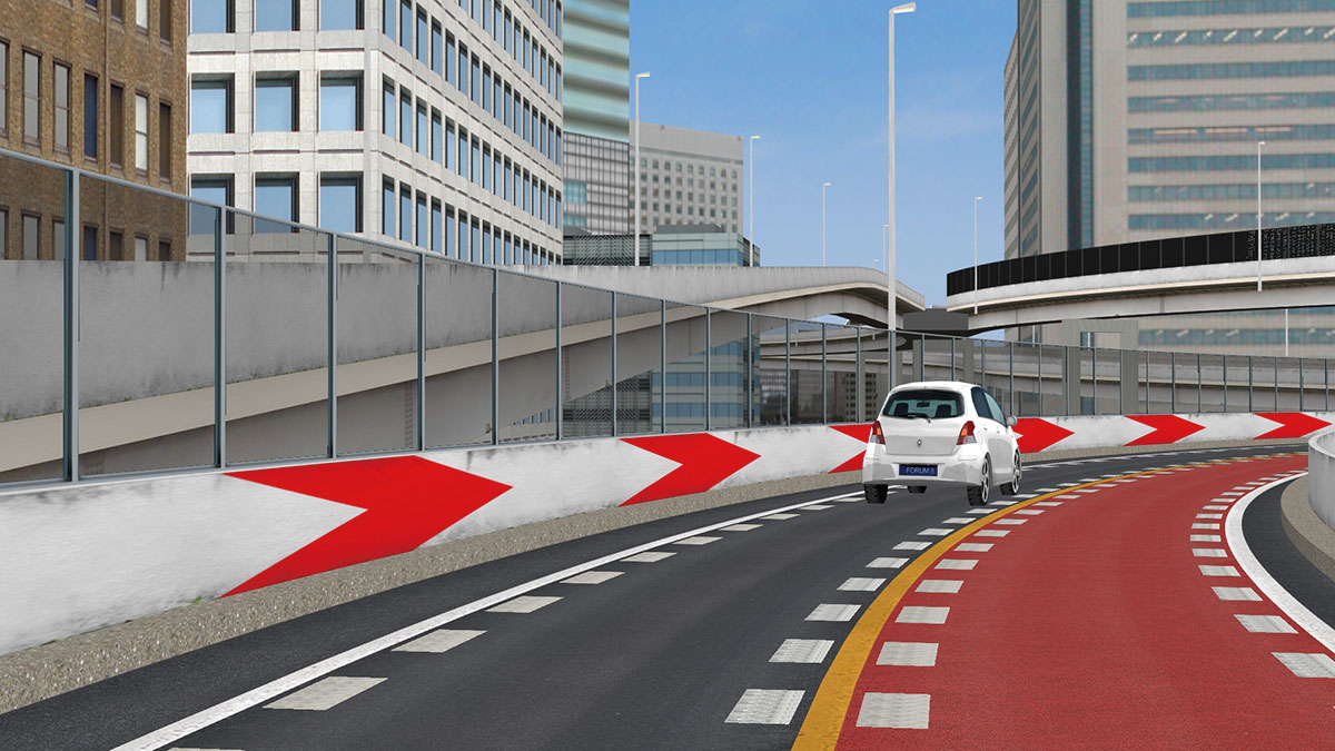
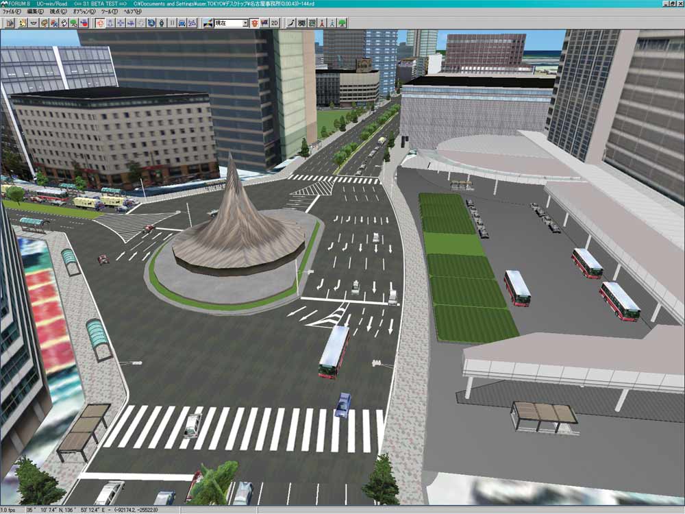
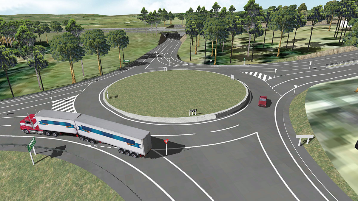
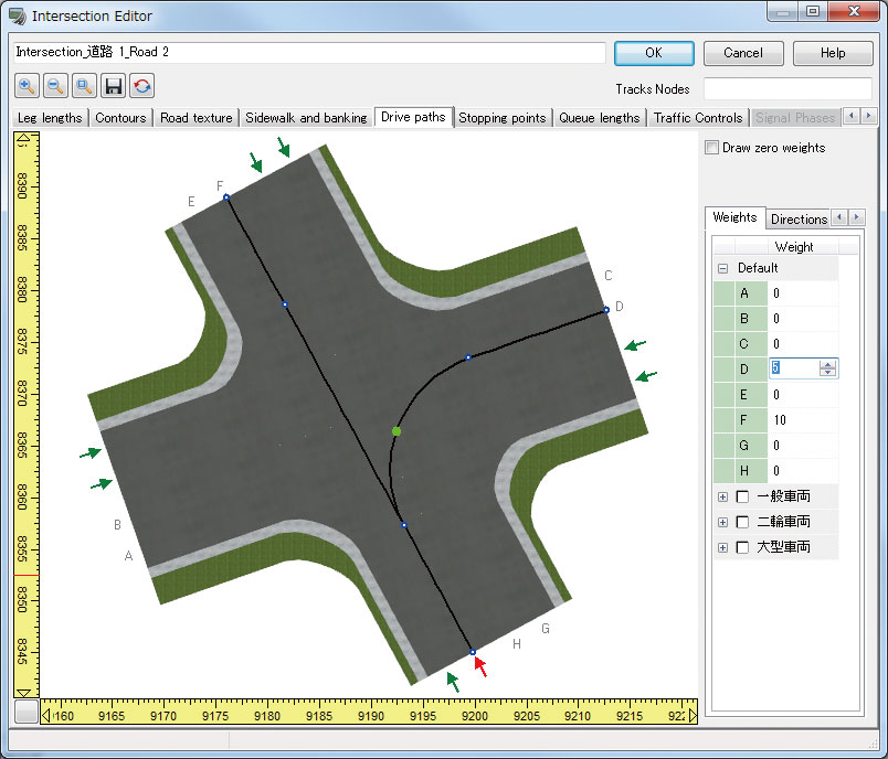
●Enhanced intersection function
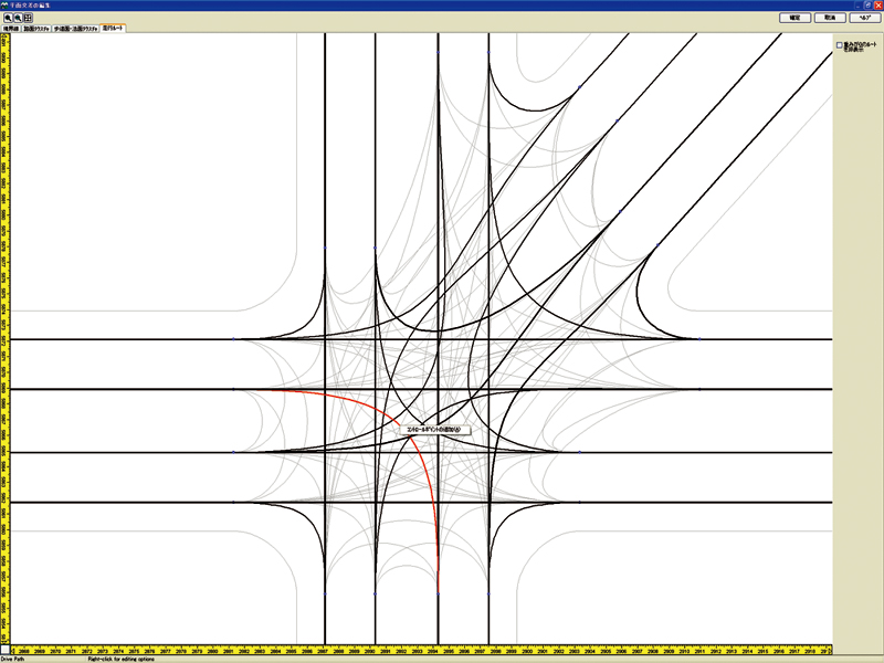
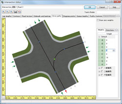
More intersection types including rotary and L type are now available for generation. Complicated flat crossing and road signs are supported through 3DS output editing. The improvement realizing for vehicles to run on the model at intersection was added.
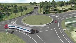
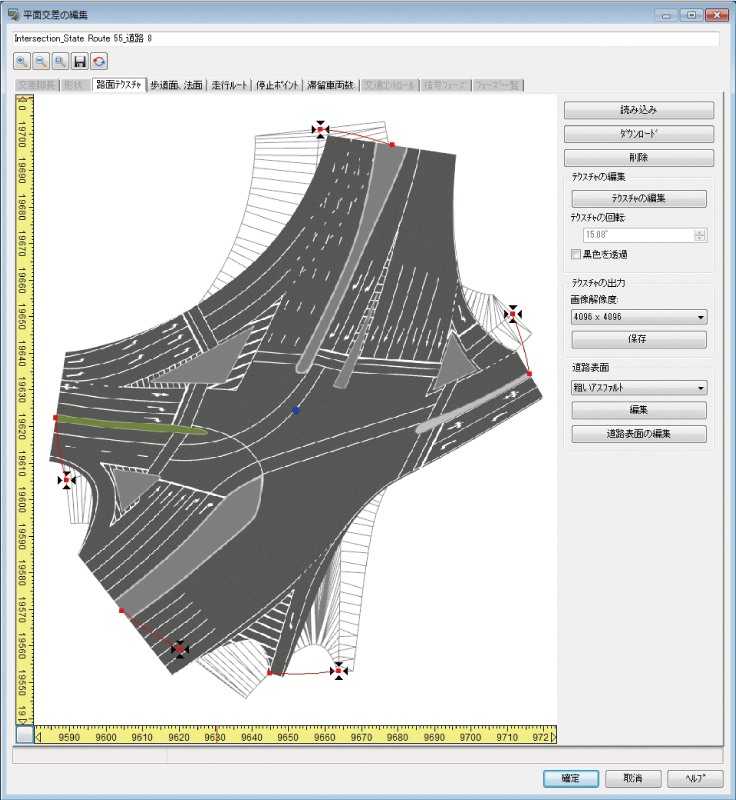
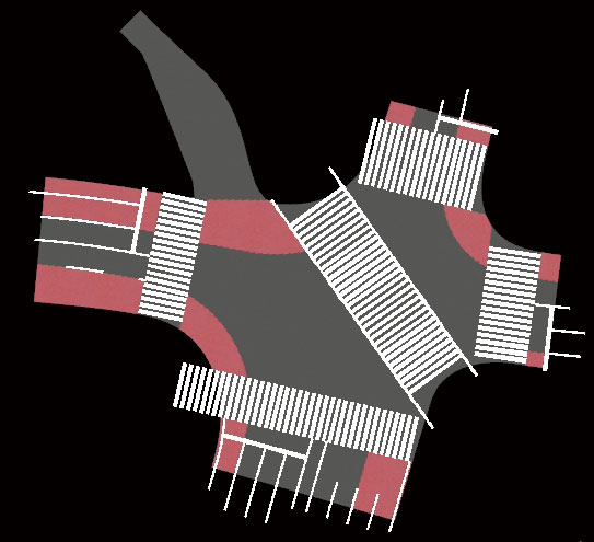
●Tool for editing intersection
The function to generate road surface texture semi-automatically. It reduces the work load of texture generation work.
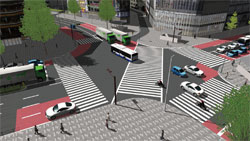
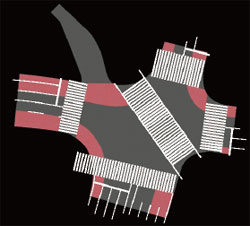
●Tool for editing building
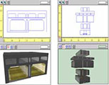
Users can create 3D building models in any shape they wish whether it is square, circle, free form, or a combination. It shows the front-back, right-left, height and size and texture of surface for both day and night.
●3D text
Generation and arrangement of 3D text on 3D space are available.
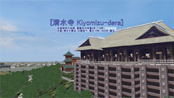
●Video wall and video player
Animation video display including cylindrical screen can be reproduced as 3D object.
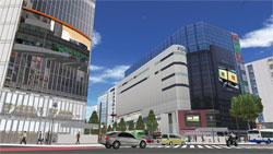
▲ Videos can be played on the curved surface.
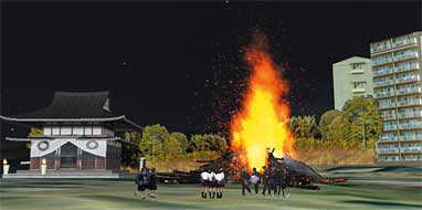
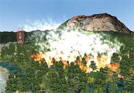
●Visualization of fire and smoke
With this function, you can present various phenomena including fire, bonfires, stream from hot springs and smoke from chimneys. The visualization and movement of smoke and fire inside tunnels is significantly improved.
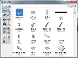
●Parametric 3D modeling
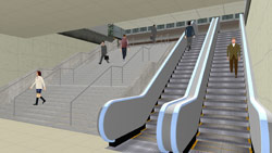
Sing, stairway, escalator, fence by parametric input can be generated. In case of stairway, the width, height, number of bars and texture can be assigned.
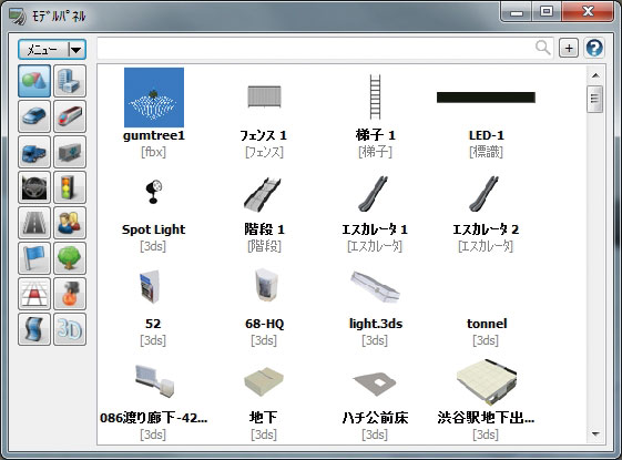
List of model panel
general model / vehicle / cab / 3D cockpit / road structure / flags / terrain texture / video wall / buildings / rail trailers / trailers / signals / characters / trees / fire and smoke / 3D strings
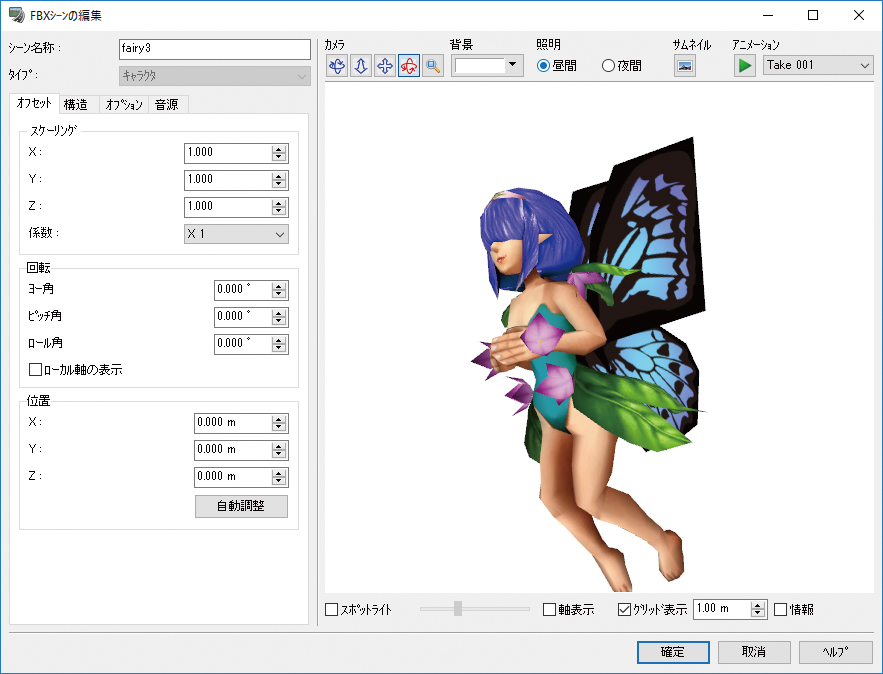
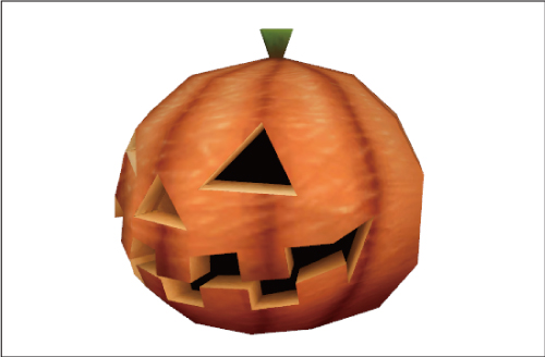
●FBX 3D model
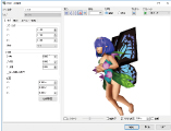
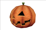
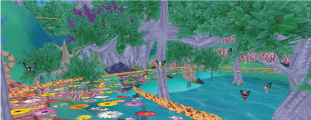
FBX file used for various kinds of models which have high accuracy is now supported. It supports the animation function using bone and allows to set the degree of transparency information and lighting effect and even to import Collada file including SketchUp etc.
●LOD (Level Of Detail) function
LOD (Level Of Detail) Function is be used in the display of the MD3 Character, 3D Model, FBX Scene
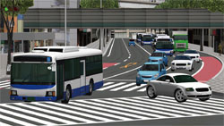
●DWG and DXF Import / Export
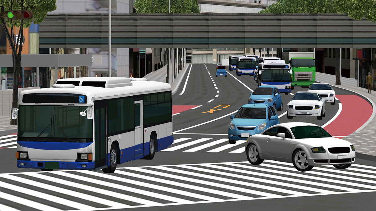
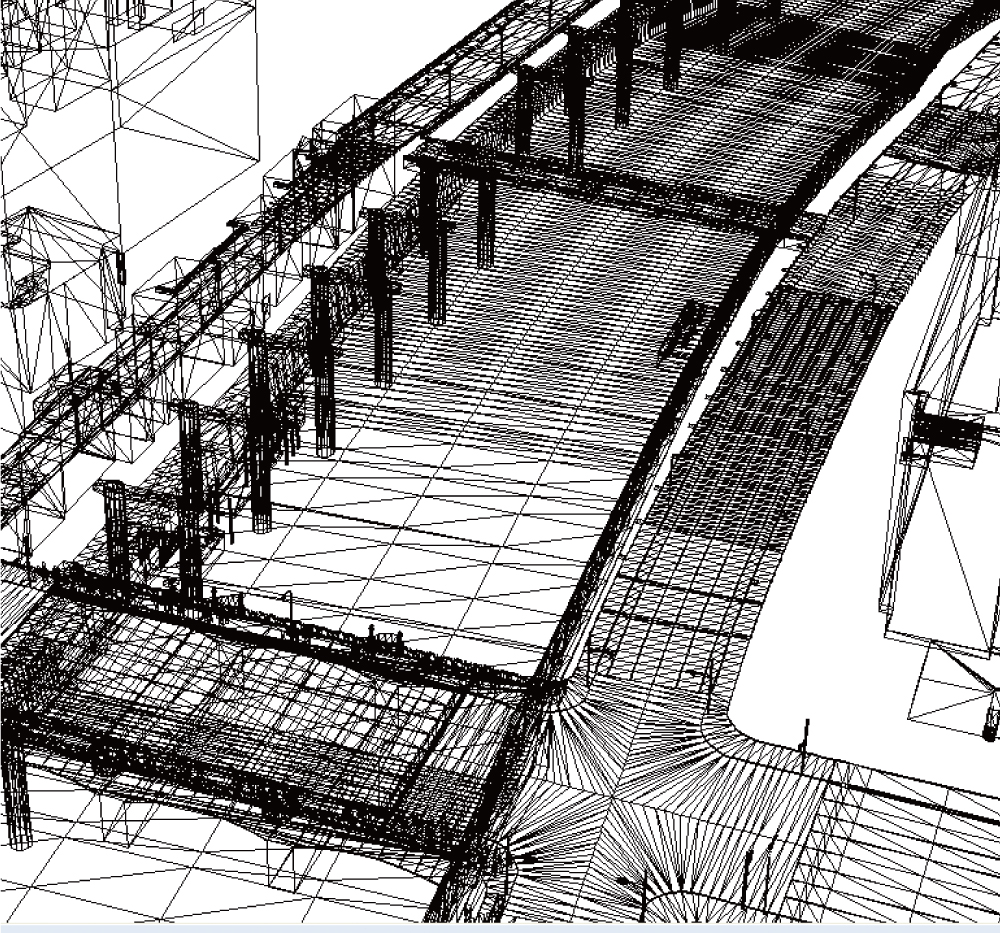
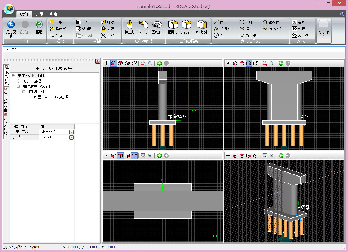
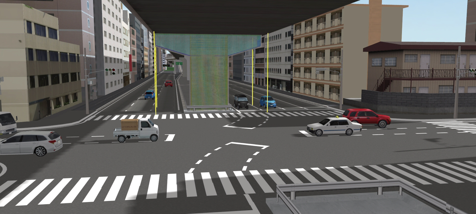
A breakthrough function to support CIM
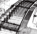
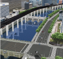
●Promoting the enhancement of CIM solution by using the cooperation between 3DVR and CAD
The 3D CAD format used in the 3DCAD Studio® can be imported to the virtual environment in the UC-win/Road directly. The IFC format is also available.
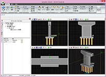





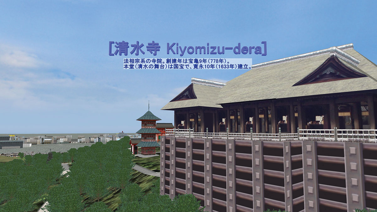
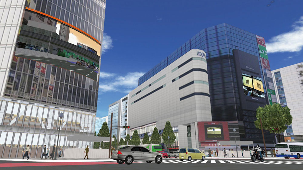
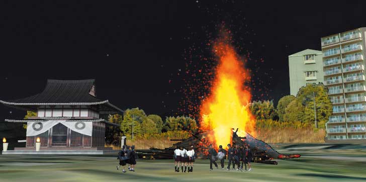
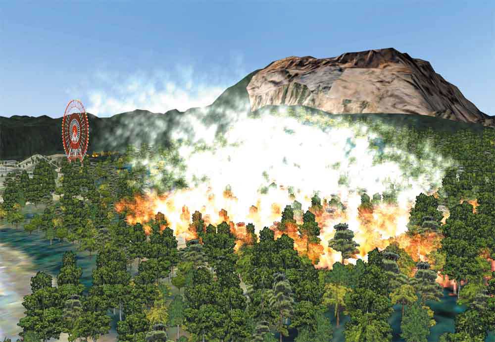


Visual Expression & Presentation Features
-
●PBR (Physically Based Rendering): Realistic light simulation can be created more intuitively.
Material function, GLTF file import function, Image Based Lighting, integration of lighting functions
The rendering method has been updated to the PBR, which models light behaviour based on physical principles. It provides easy parameter settings and the ability to obtain realistic rendering results.
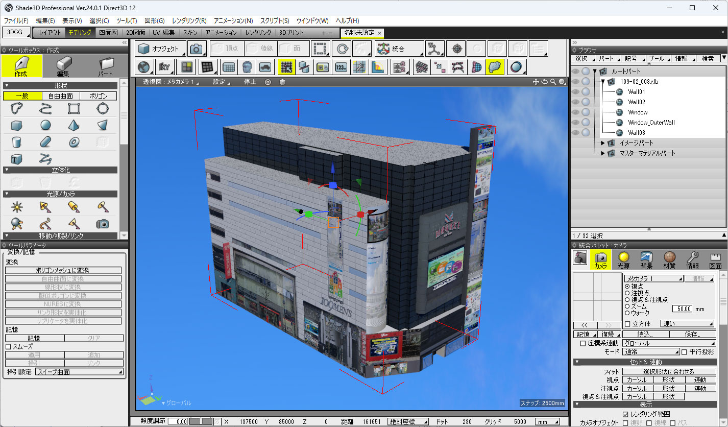
Furthermore, it represents natural scattering and reflection using image-based lighting, detailed unevenness using normal mapping, and realistic color reproduction using linear workflow. In addition, it also supports loading GLTF format, allowing for seamless integration with Shade3D and other engines.
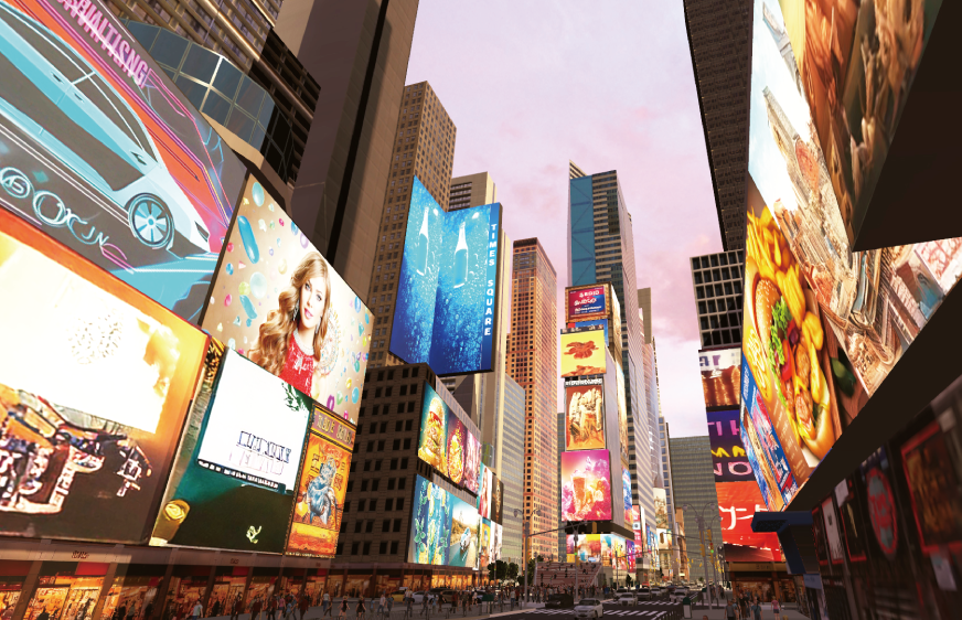
After PBR implementation
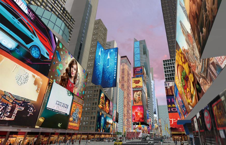
Before PBR implementation
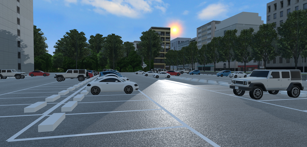
Reflections from uneven asphalt road surfaces
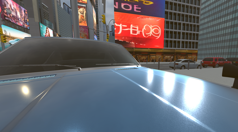
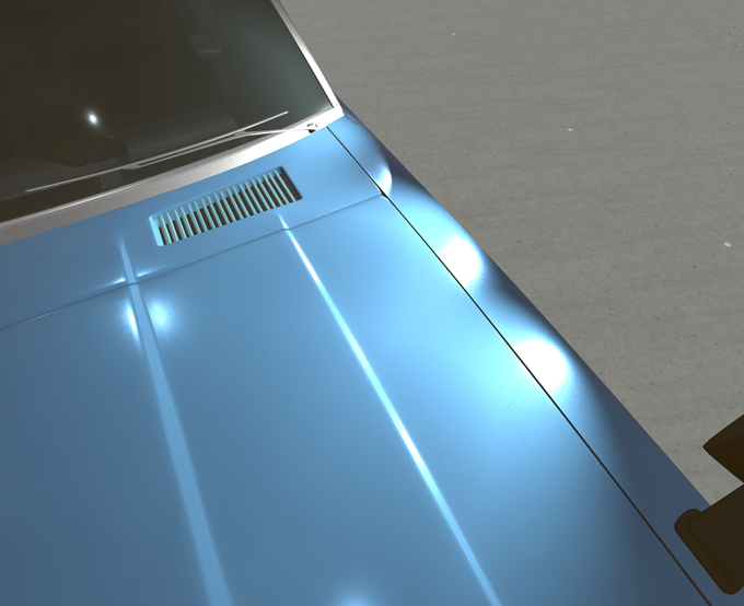
Reflections from vehicle body coatings
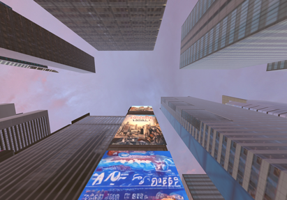
IBL (Image Based Lighting) expresses the reflection of sunset on buildings.
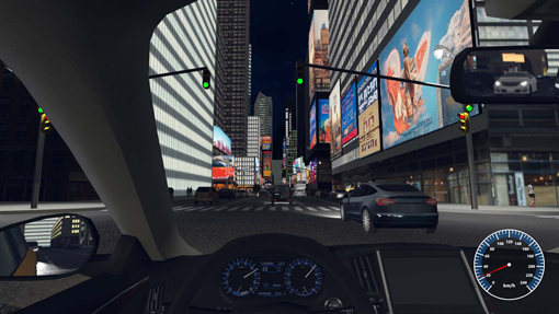
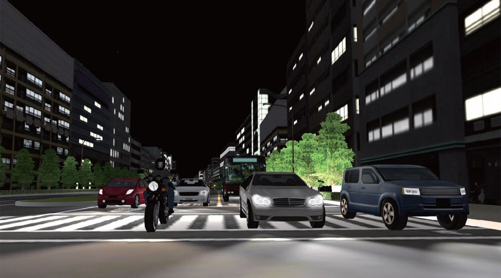
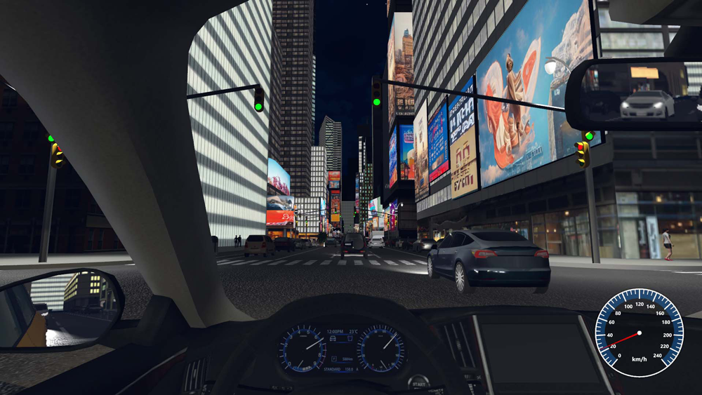
In night scenes, lighting effects such as street lights, vehicle headlights, and taillights are supported.
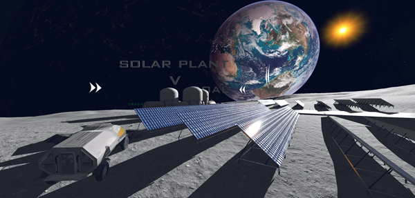
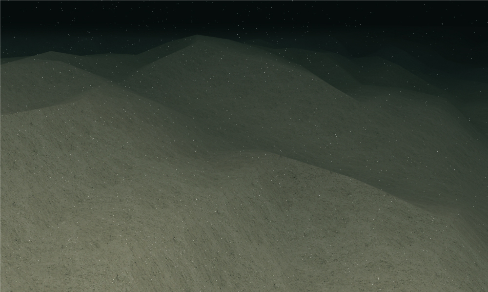
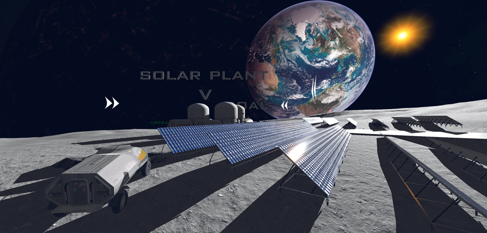
Reproducing the differences in direct light and shadows in a space environment, as well as the reflective properties of rocks and sand
GLTF file import
It is possible to read GLTF and use it as a 3D model in UC-win/Road. GLTF can also store material information for physically based rendering, such as normal mapping, metalness, roughness, and refractive index.
In addition, it is possible to output GLTF files from Shade3D, so you can use them to import data created in Shade3D. Model files can also be used with the F8VPS and VR-NEXT engines.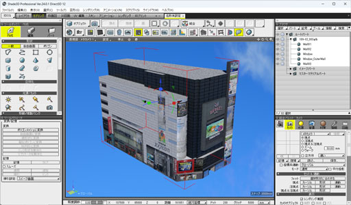
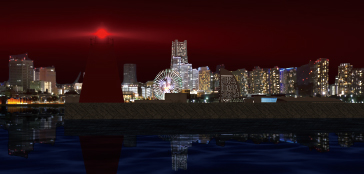
●High precision rendering (auto-creation of shadow / water reflection / sky)
Sky condition according to time and water reflection can be automatically created. Performance and quality of the shadow rendering are also improved.
●Visualization of fire and smoke
With this function, you can present various phenomena including fire, bonfires, stream from hot springs and smoke from chimneys. The visualization and movement of smoke and fire inside tunnels is significantly improved.
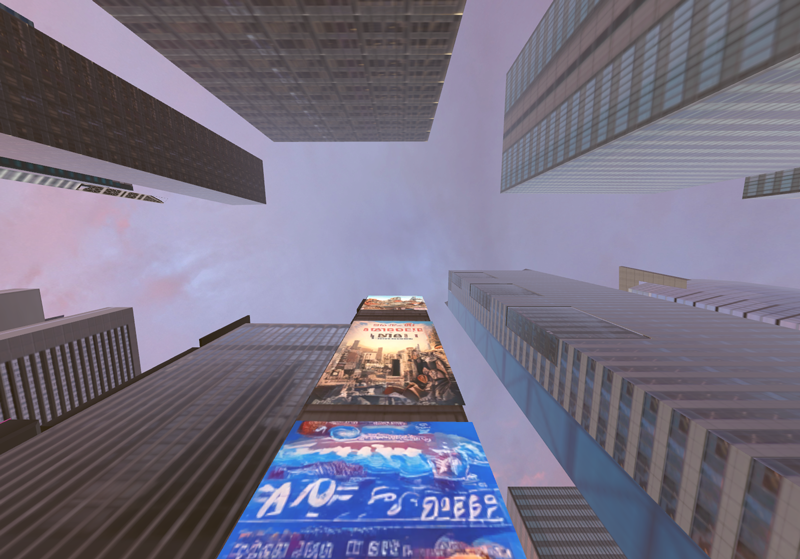
●Sky dome function
The Sky dome function is where the sky can be rendered inside of the 3D environment. It is now possible to map various textures on it.

Traffic Simulation
-
- Packetization of vehicle
- Setting probability of each route group
- Motion control point in the event transition
- Setting the number of stranded vehicles
- Scenario within an intersection
- Save traffic conditions (Control scenarios/scripts/contexts using traffic snapshot function)
- Improvement of scenario function
Vehicle speed, lane(s), speed limit can be dynamically assigned. Various commands against leading vehicle (can be applied to traffic flow, vehicle within a scenario played by Micro Simulation Player) - Linkage with VISSIM 2023
- VISSIM TCP linkage
UC-win/Road and VISSIM can be linked even if they are installed on the different PCs. - VISSIM Multi User
When a cluster linkage is established and the master PC is cooperated with a VISSIM, the vehicles operated by the multi-user client are also sent to VISSIM. - Addition of start point, end point, and average amount of pedestrian
- New types of pathway (train station, stairs, escalator)
- Link (elevator, waiting room)
- Multiple pedestrian profile
- The shortest pathway search algorithm
●Traffic simulation function
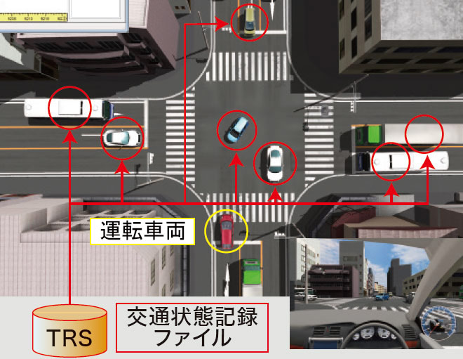
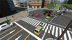
●Signal control / Traffic simulation with road hazards
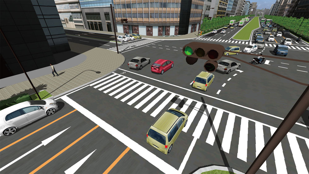
Traffic simulations based on vehicle performance are supported. It is compatible with various traffic rules, signal control and traffic lane control, and car lights and signal expression in traffic simulation are available.
●Traffic rules setting
Traffic rules for Japan, New Zealand, China and Korea are loaded by default and moreover new rules can be added freely.
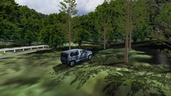
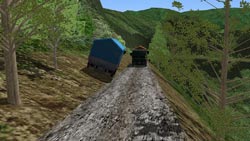
●Off-Road function
Users can drive vehicles around the 3D VR space using a steering wheel, a game controller or the keyboard in UC-win/Road.
●Traffic connector
The virtual type which connects between moving nodes can be defined and the traffic movement can be set from edit window of plan view or main menu.
●Vehicle configuration/waypoints
Configuration of driving routes, starting positions, running behind other vehicles (e.g. trains), sound configuration and railroad crossings, by setting action control points, is available.
●Display revolving wheels, steering angle
With vehicle plug-in, displaying revolving wheels and the steering angle is possible by defining the front and rear wheels.
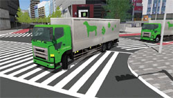
●VISSIM
Visualization of traffic analysis reading the result of traffic analysis of VISSIM.
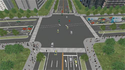
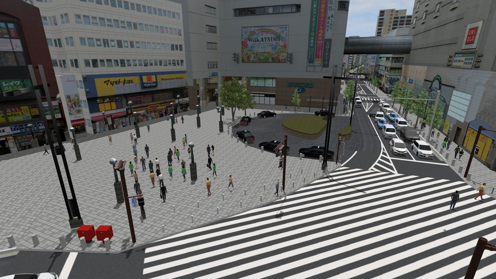
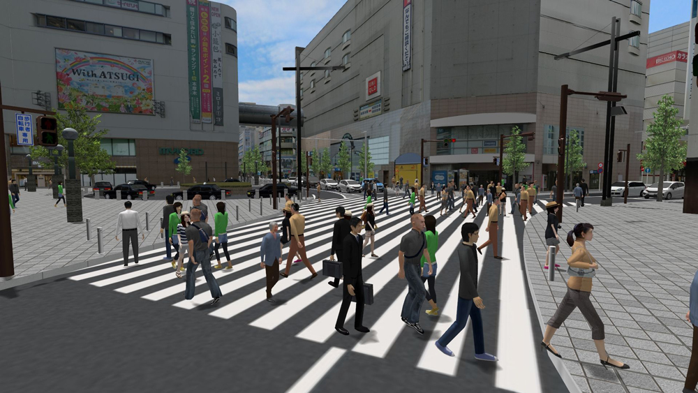
▲Vehicle and pedestrian flow analysis by VISSIM is imported into VR (The 21st 3D VR Simulation Contest on Cloud Essence Award
"VR Simulation Reproducing Traffic around Hon Atsugi Station" Oriental Consultants Co., LTD.)
●Interaction function
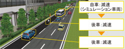
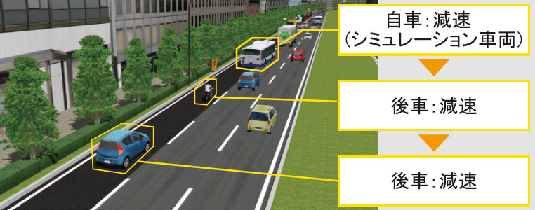
The interference check on the traffic flow and self-vehicle course generated from various traffic analysis software, such as VISSIM and S-PARAMICS.(within less than 200m) The oncoming vehicles decrease speed automatically.
●Navigation
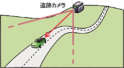
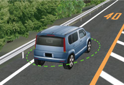
Dividing movement mode and simple viewpoint operation clearly, support the viewpoint operation in a movement mode.
Movement mode Possible viewpoint operation Free movement Rotation, moving back and forth horizontal and vertical movement,
free flight, satellite movement, jumpRunning, Flight, Driving Rotation, rotation on an axis of object, satellite movement Walking Rotation, jump Chasing Rotation centering around object, satellite movement
●Special weather effect and illumination
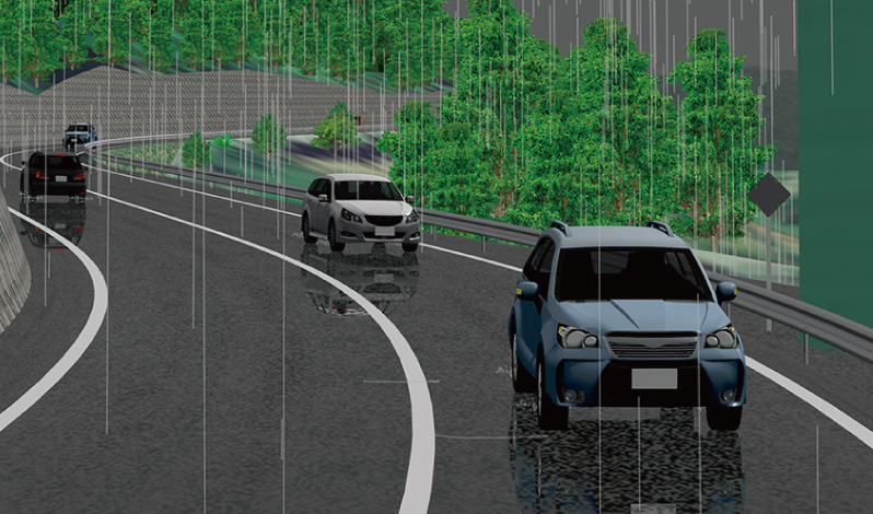
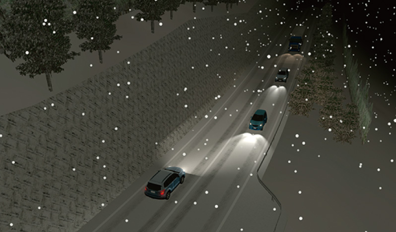
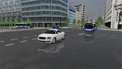
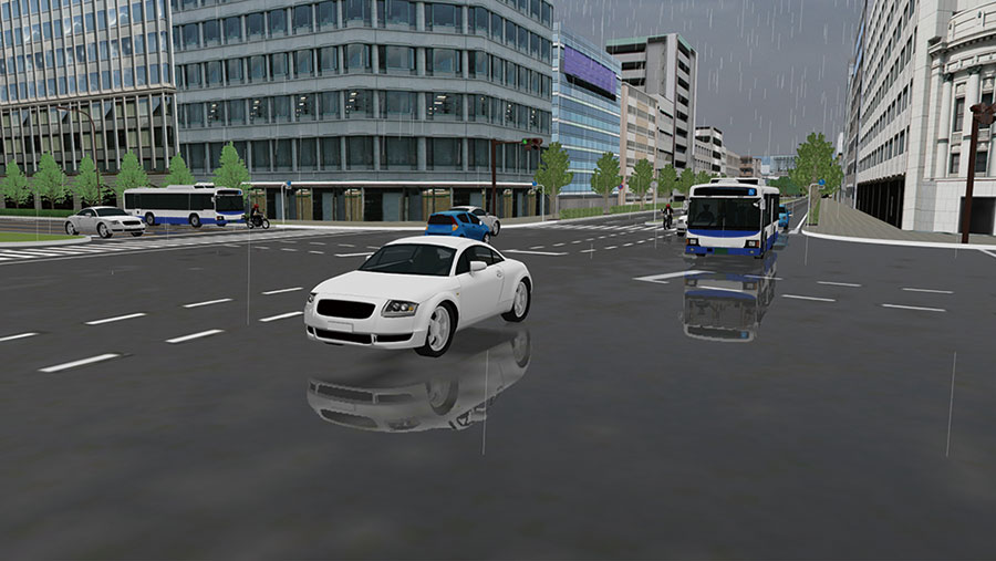
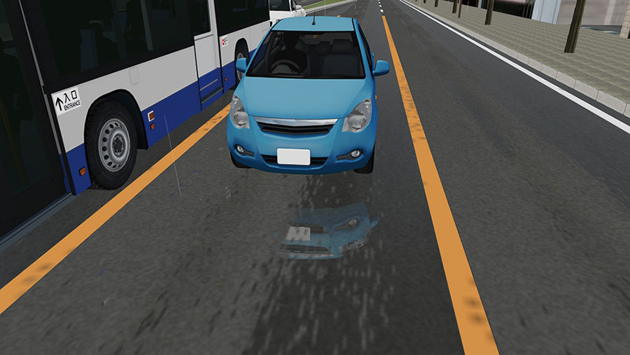
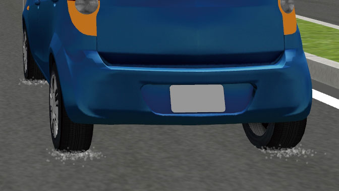
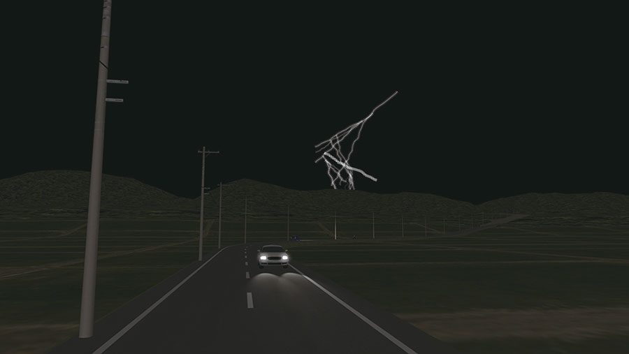
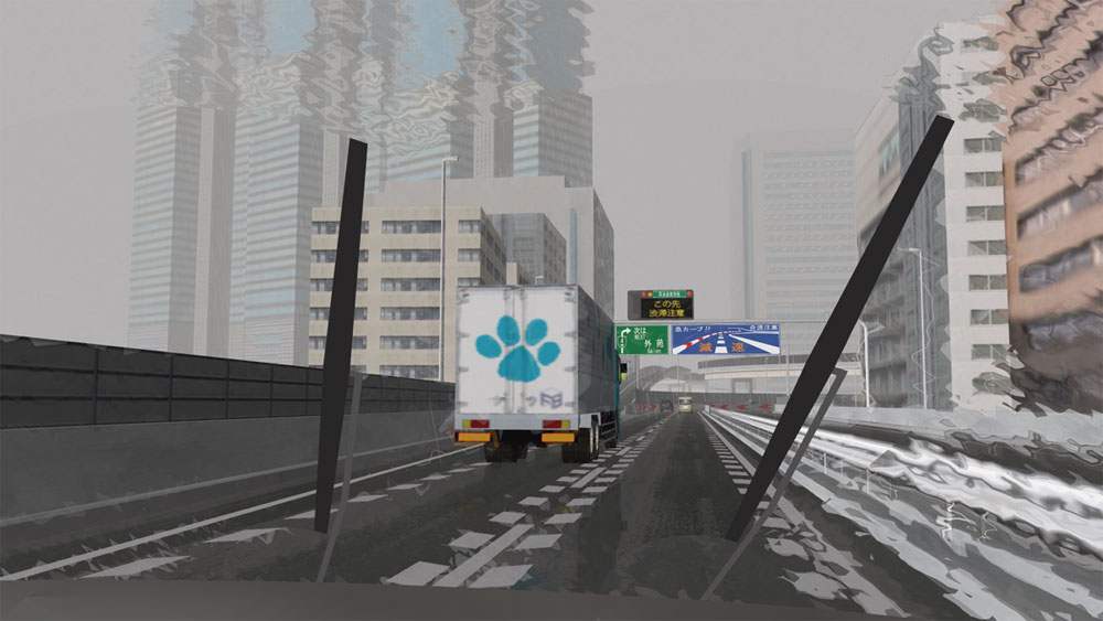
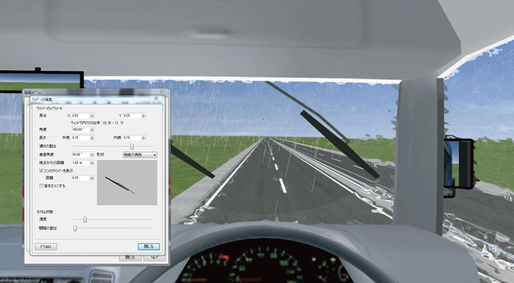
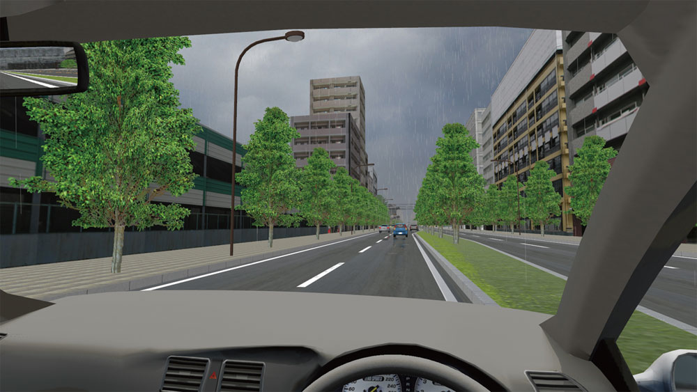
The function of rain and snow expression is lifelike. Fog, thunder, wiper(Can be operated with the axis of the upper surface of the windshield) and water splashing can specify the execution area.
▲Road surface
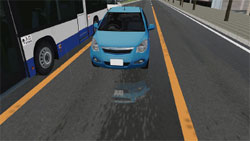
▲Water puddle
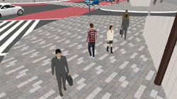
▲Rain ripple
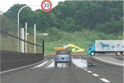
▲Road mirage
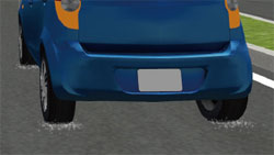
▲Water splashing
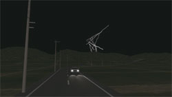
▲Thunder
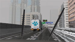
▲Windshield wiper (rain)
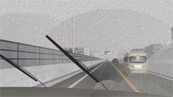
▲windshield wiper (snow)
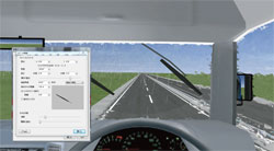
▲Wiper (Bus/Heavy-duty truck)
●Walking simulation
Speed alteration while walking is available. Walking operation with mouse was added.
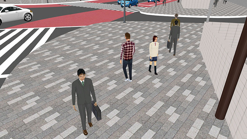
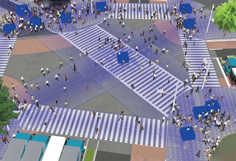
●Movement of walking crowd
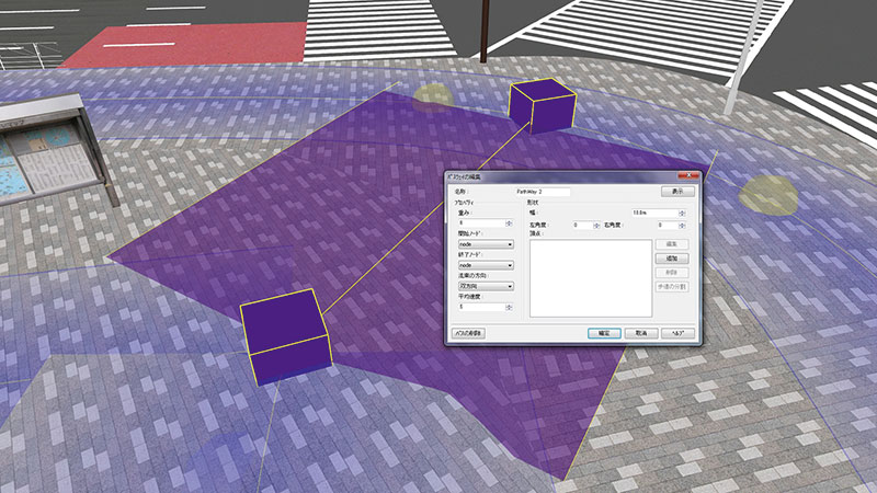
Pathway arrange in 3D space, Setting of many pedestrians
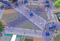
▲Crash avoidance
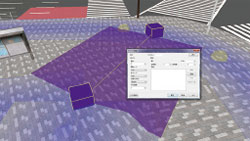
▲Pathway setting
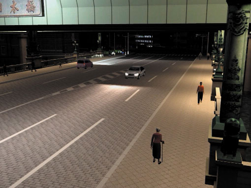
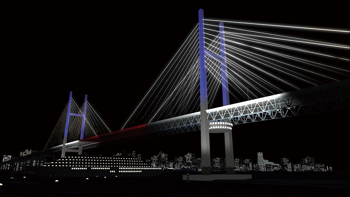
●Artificial light/Shading
A simulated lighting feature is offered by alternating textures for day and night. It will turn to night texture automatically in tunnel.
●Lighting function
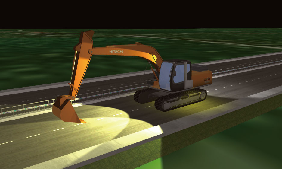
The spot light and head light function allows the simulation of night time and lighting. For instance, you can use it for a signal lamp, a window lamp in a building or the light of a vehicle.
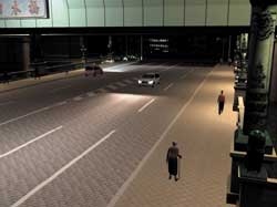
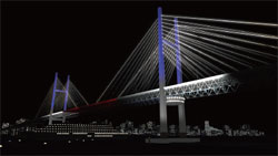
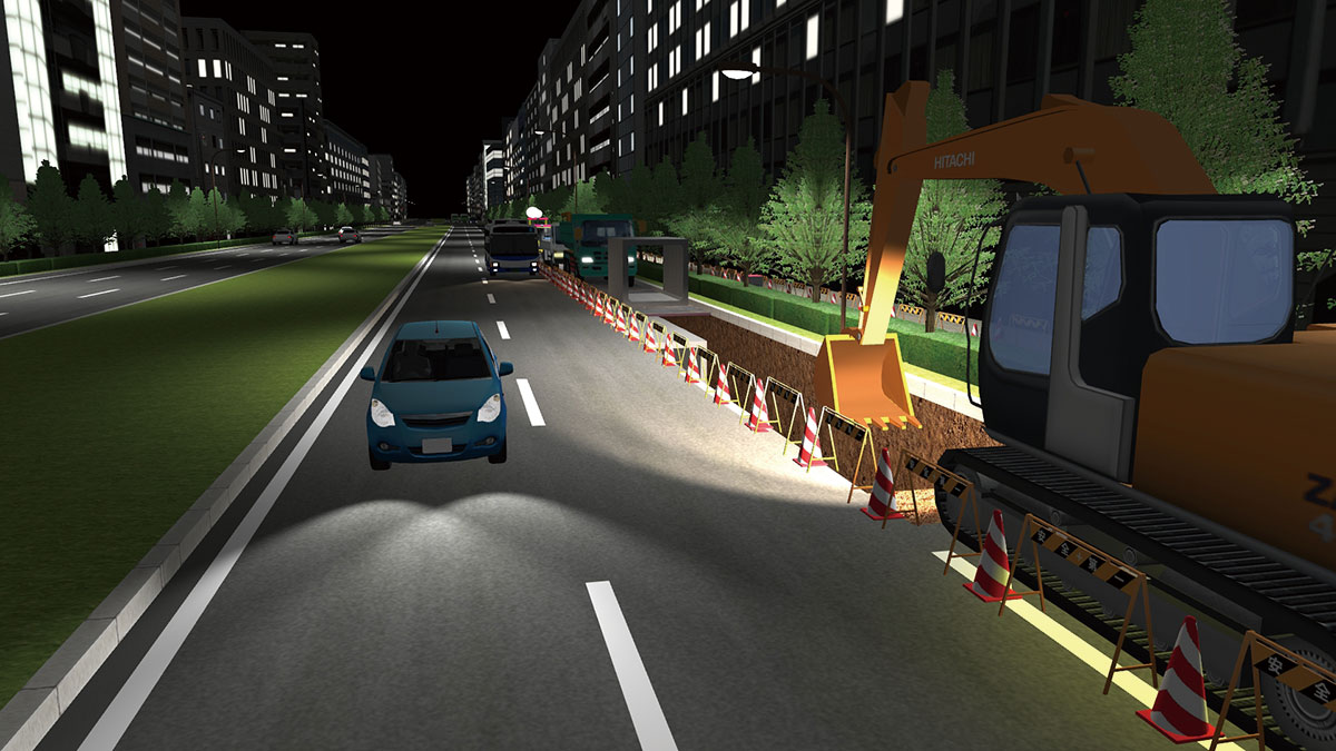
●Headlight
Can be set individually for each vehicle. Rear lamps, backlights, fog lamps, side lights, 10 extension lamps, and the lights of special vehicles like heavy machine in addition to current brake lamps, winkers, and hazard lights.
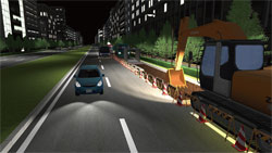
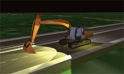
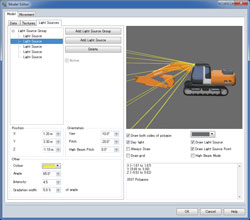
▲Lights of special vehicles
like heavy machine
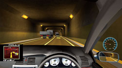
●Tunnel lighting function
Setting the color and strength of tunnel lighting is available. The effect is applied to the traffic vehicle going into tunnel and an adjunct of road.
●Context (Environmental conservation)
The function which can save various environmental setting in one context and are able to execute context in one click.
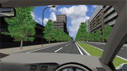
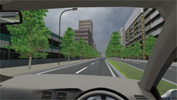
●3D stereo display
Passive method which outputs the image to multiple screens with parallax, and Active method which outputs to one screen from side to side using Quadro video tip, produced by NVIDIA are supported. Wide-screen can be available.
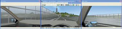
▲Left-eye
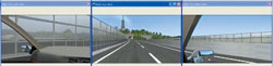
▲Right-eye
●User variable number: scenario control, log output
●Object reference function by object custom ID








Driving Simulation / Vehicle Research and Development
-
- Speed designation: Follows a specified speed strictly.
It can be applied to the travel in direction along the road and in any direction. - Acceleration designation: Follows a specified acceleration and deceleration strictly.
It can be applied to the travel in direction along the road and in any direction. - Keep distance between other vehicles: Travels while keeping the distance to the object vehicle.
- ABS (Anti-lock Braking System) is now supported.
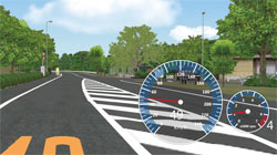
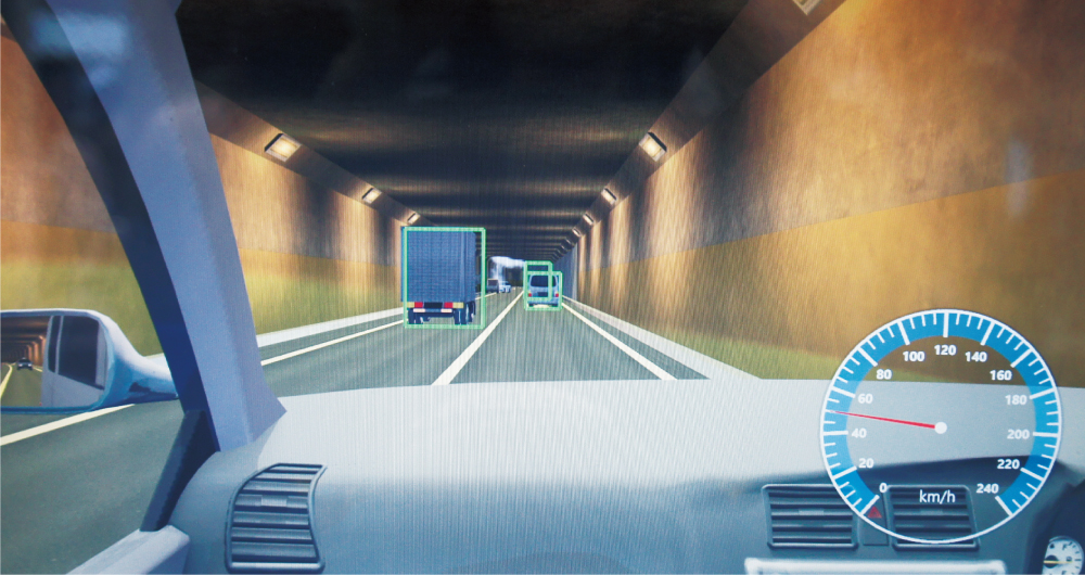
- Dashboard can be displayed.
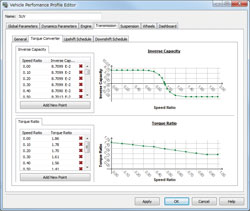
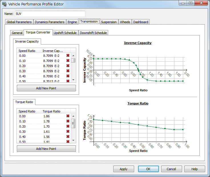
- Corresponds to torque amplification and creep phenomenon in automatic cars
- Significant improvement in that the characteristic of torque converter, which tranfers rotating power from an engine to the transmission, are modeled very precisely in car with an automatic transmission.
- The concept of half clutch control has been added.
- Auto speed control
- Auto steering control
- Brake assist
- Superimposed display of the leading vehicle's information
●Manual driving
Support for manual driving as well as traffic flow based on vehicle performance by vehicle type.
* The manual driving requires steering controller (steering wheel and accelerator) that is sold separately.
●Vehicle cockpit setting
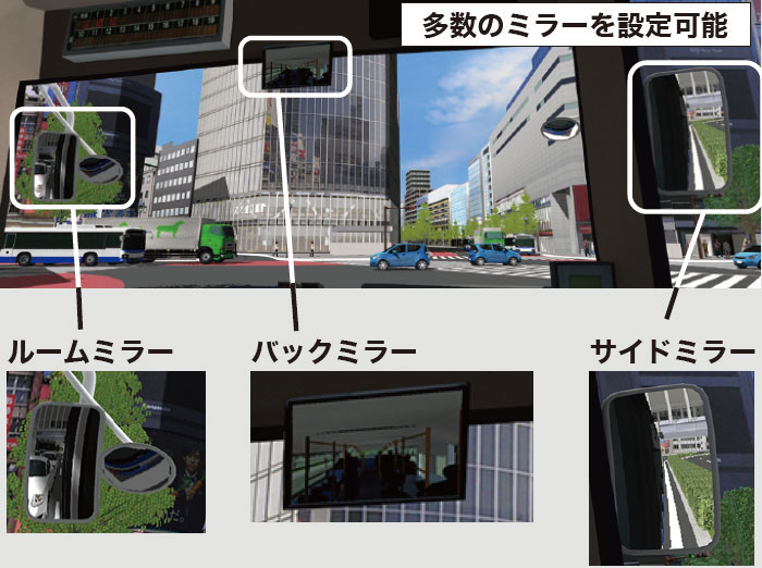
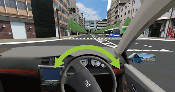
Side mirrors, rear-view mirror, and car navigation system (display any view) can be displayed in 3D cockpit in real time. Multiple mirrors can be set to 3D cockpit model parts of a large truck and heavy vehicle. Steering rotation is also drawn.
●UC-win/Road Driving Simulator
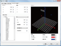
▲Setting of mirror
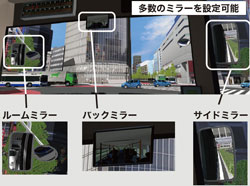
▲A number of mirrors can be set
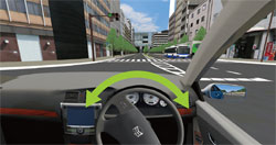
●Vehicle control
Types of describable car lamps have been expanded, and you can describe and control rear lamps, backlights, fog lamps, side lights, and 10 extended lamps in addition to current brake lamps, winkers, and hazard lights. The Micro Simulation Player feature plays previously recorded motions for scenes that reproduction is required, but the following vehicle control mode will be added.
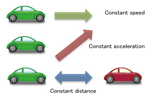
▲Keep distance to other vehicle
●Constitution of vehicle movement model
The expression of more realistic movement is now available by implementing model of overall vehicle movements, engine and each transmission from engine to wheel.

●Driving simulation function
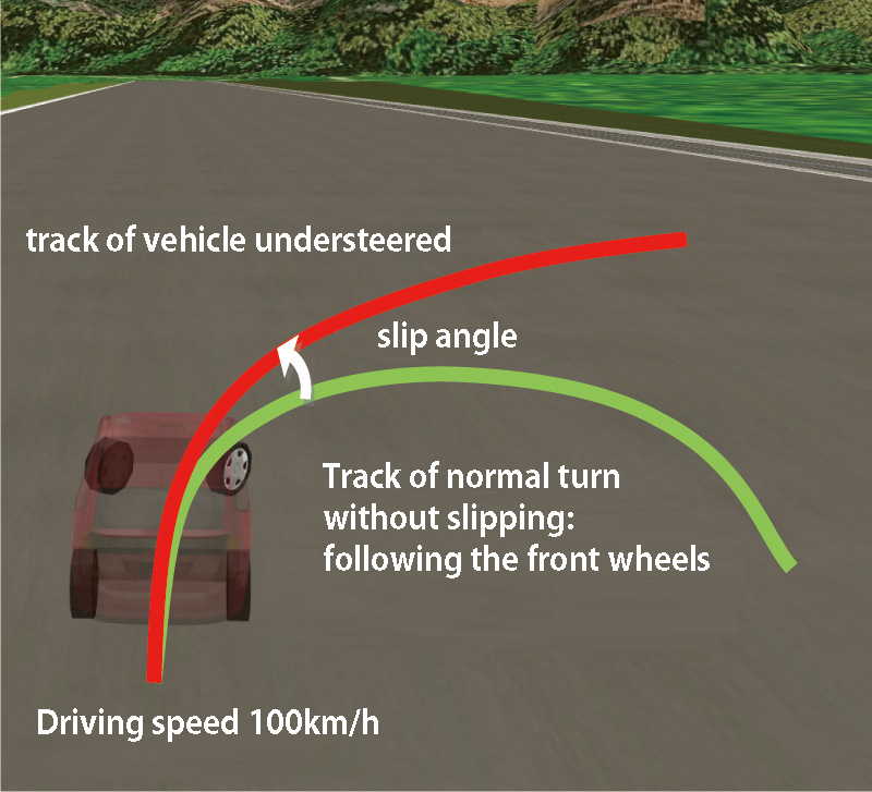
As vehicle dynamics model that accurately calculates vehicle's physics is included in UC-win/Road, it is possible to perform calculation taking into account the engine, transmission, vehicle weight and center of gravity, tire's frictional coefficient.
●ACC/Automatic driving function
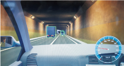
ACC function and self driving function in driving simulation are added. It can switch the manual driving and automatic driving. It also allows to recognize the traffic signals and limited speed.
●Calculation frequency control and SILS function
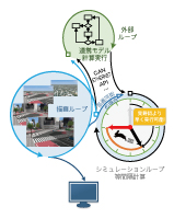
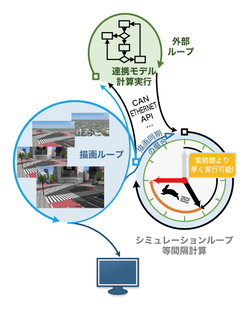
In automobile R&D, it is common to run simulations of automobile and its equipment at regular intervals. Until now, UC-win/Road synchronized visualization and simulation calculation, and performed them at the same cycle, depending on the PC's computation power.
Cycle was variable according to VR data contents. It could run simulations flexibly regardless of the kind of used content, but it was difficult to calculate in the accurate frequency.
In UC-win/Road Ver.12, the calculation cycle and image update cycle can be set separately. A variety of patterns are available according to user's simulation needs (calculation and display, calculation only). Each combination and its purpose of use is shown in the following table.
Internal timer can also be customized with SDK.
Calculation time step Display synchronization Internal timer Explanation of system operation Applied ON - Synchronize calculation and display along to the real time. Frame rate is variable according to their burden. Applied OFF - Along to the real time, FPS becomes high depending on the CPU performance in simulation calculation.
Display depends on the computer performance, and lower FPS than the simulation calculation is used.Fixed ON ON Simulation calculation rate is fixed and all frames are shown.
Execute along the real time if at all possible (it will be slower than the real time if burden is heavy).Fixed OFF ON Simulation calculation rate is fixed. Show only frames that can be shown according to its display performance.
Execute along the real time if at all possible (it will be slower than the real time if burden is heavy).Fixed ON OFF Simulation calculation rate is fixed and all frames are shown.
FPS becomes high depending on the CPU performance (not consider the real time).Fixed OFF OFF Simulation calculation rate is fixed. FPS becomes high depending on the CPU performance (not consider the real time).
Display depends on the computer performance, and lower FPS than the simulation calculation is used.
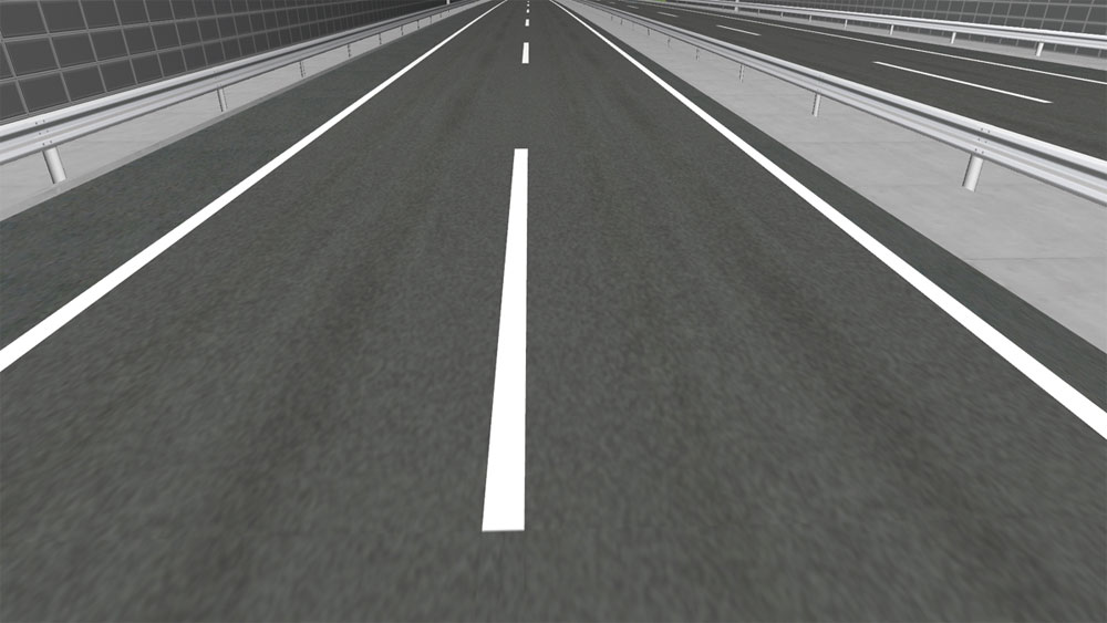
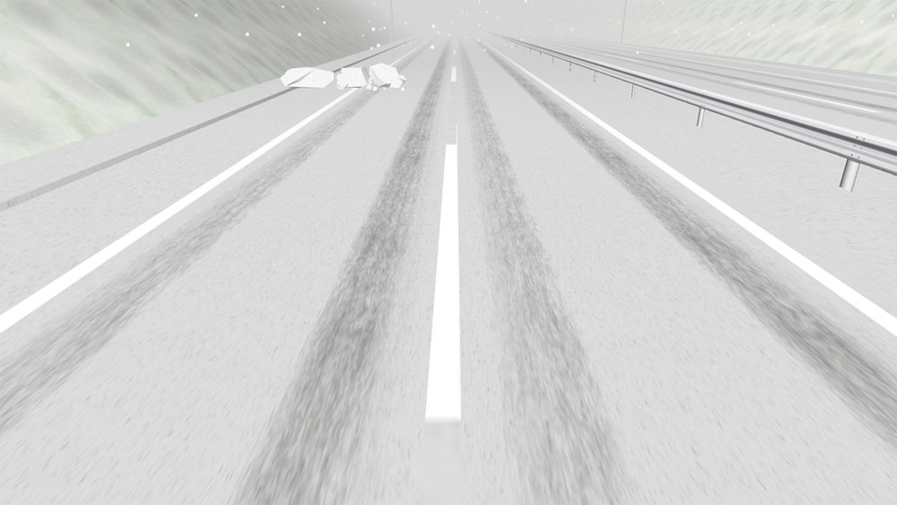
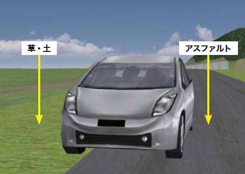
●Road attribute
Setting the difference of friction coefficient on road surface in every texture is available.
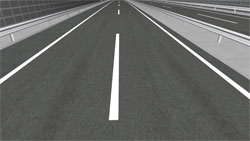
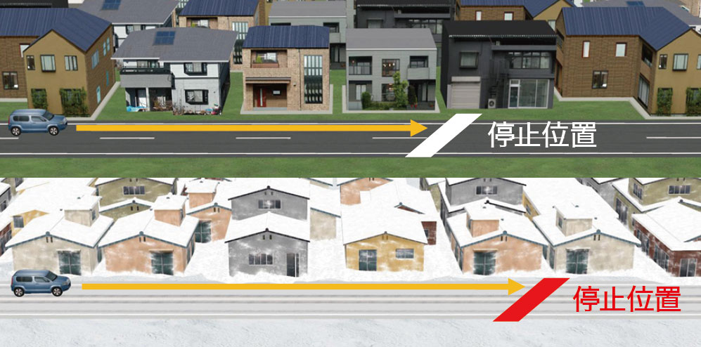
▲High grip road surface
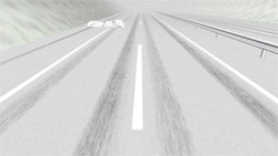
▲Slippery road surfaces (Snow-covered road)
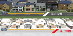
●Audio system
By employing OpenAL, a variety of surrounding sound, the car's sound (sound of engine tire, wind, tunnel reflection sound) are supported.
Lowpass filter is supported. Squeal sound (slip sound) and sound reproduction of 4 different wheels are supported.
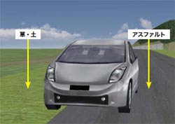
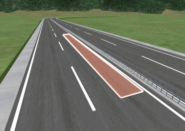
●Force feedback
Automatic vibration deriving from road material and road shape and constant vibration within the area is transferred to the controller.
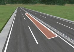
▲Oscillation region
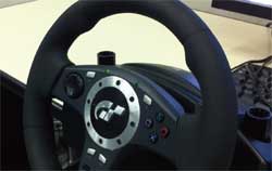
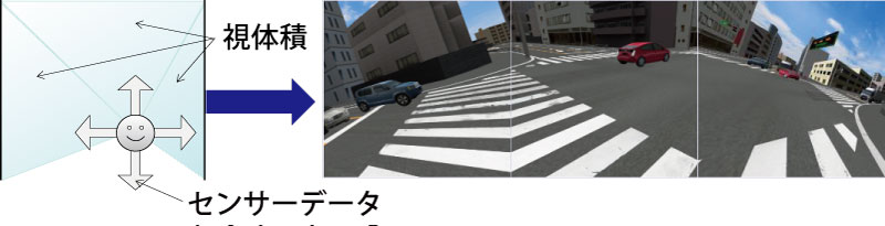
●CAVE system
Calculates and draws visual volume based on the positional relation between the screen and the user. The viewpoint and view volume are updated by trackind the position change of the user with any device.
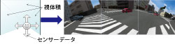
●Head tracking
The head tracking function is a plug-in used for receiving a driver's eye position information while he/she is driving in real-time from sensors such as Kinect, and sending that information to UC-win/Road itself.
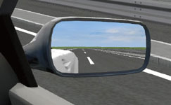
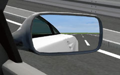
▲View in side mirror changes
●Edge blending
When projecting via several projectors, the screen on the edges between the projectors can be smoothly displayed. Pitch angle of the projector is also supported.
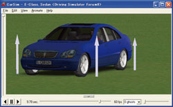
●Linkage with CarSim
Realistic vehicle movement simulations using the set value of road friction coefficient Mu are supported.
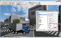
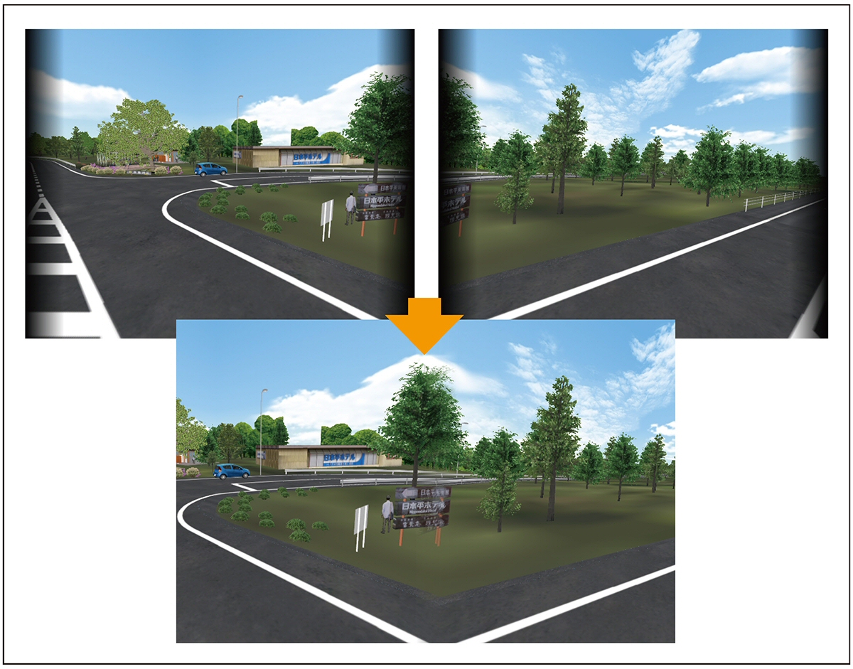
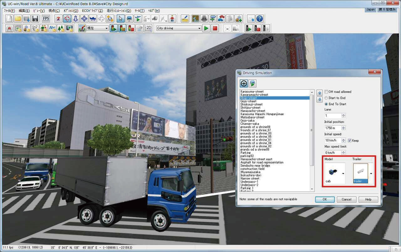
●Trailer running function
Cab model and trailer model are set separately, and they are controlled as different models are connected.
- Speed designation: Follows a specified speed strictly.



Interface
-
●Full screen, simulatin panel
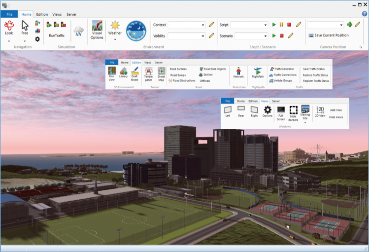
Displaying full screen is possible, without showing the menu and tool bars. Simulation which can customize its panel position and command. Ribbon interface is available.
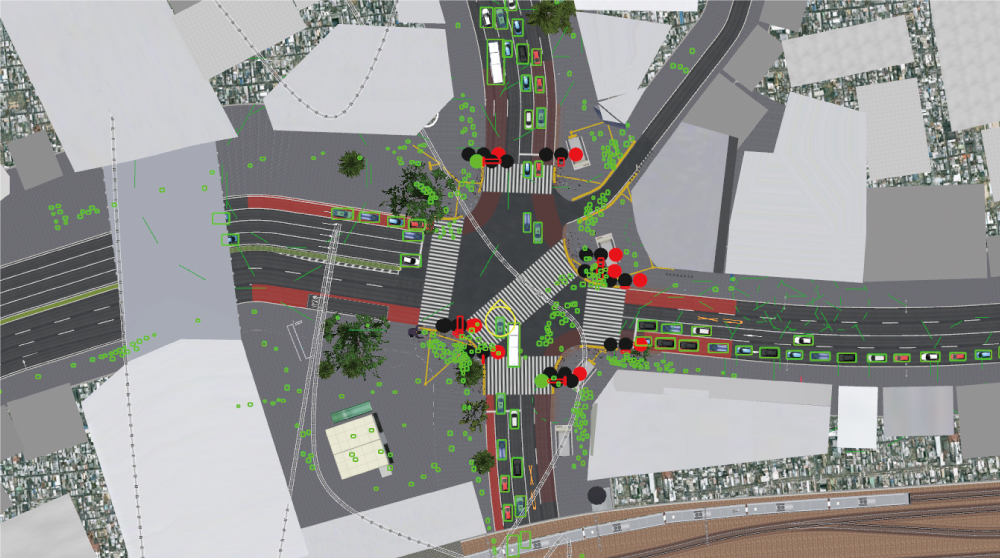
●2D horizontal plane view
Frames and information of 3D models, roads, and vehicles can be displayed. Simulation status can be seen at glance.
●3D Navigation (3D mouse)
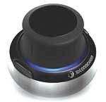
By using a 3D Mouse like "Space Navigator", you can move in the 3D space intuitively while using your mouse at a time.
●Operation via game controller and keyboard is supported.
●Universal UI plug-in
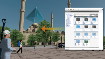
You can search and browse a variety of contents such as image, video, and web page by using a simple intuitive interface with 3D icons.
3D・VR Solution
Data integration with IFC
-
The terrain data and design and analysis data such as structures and civil structures designed by BIM CAD are linked with UC-win/Road so that they can be checked in VR space.
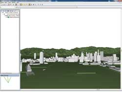
▲UC-win/Road→IFC
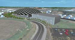
▲The example of BuildLiveTokyo 2010 utilizing IFC

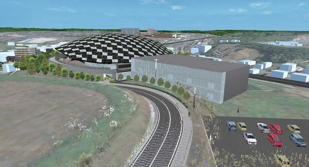
Data integration with Road CAD
-
It is total integration system to allow you to design of civil engineering, such as road/land development, VR simulation, presentation by linking with Design CAD application and UC-win/Road.
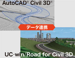
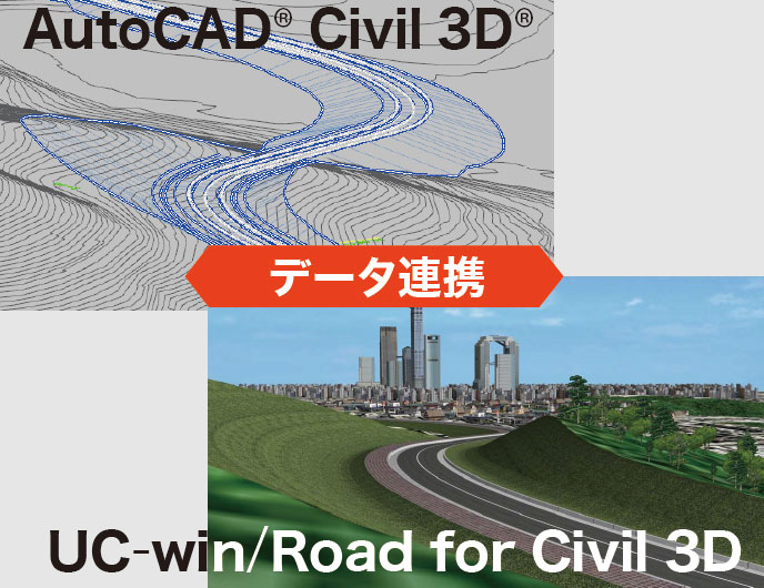
UC-win/Road can link at object level with Next generation solution AutoCAD®Civil 3D® which brings a paradigm shift to civil engineering design process.
UC-win/Road Data Exchange Tool for Civil 3D
12d allows fast production in a wide variety of projects including mapping, site layout, road, rail and highway design, residential & land developments, and environmental impact studies. Importing data of UC-win/Road to 12d Model allows to calculate soil volume and create the detail drawing.
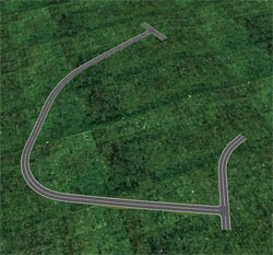
▲UC-win/Road
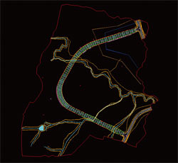
▲12d Model
●UC-win/Road OHPASS Plug-in Option
The optimal highway pass obtained by calculation can immediately be visualized in UC-win/Road thanks to its seamless linkage with OHPASS (Optimal Highway Path Automatic Search System).
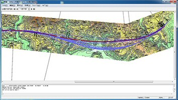

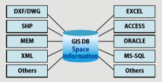
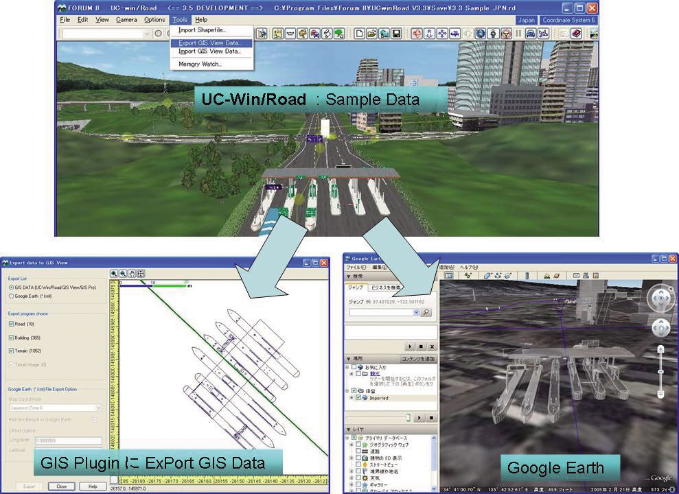
Data integration with GIS applications
-
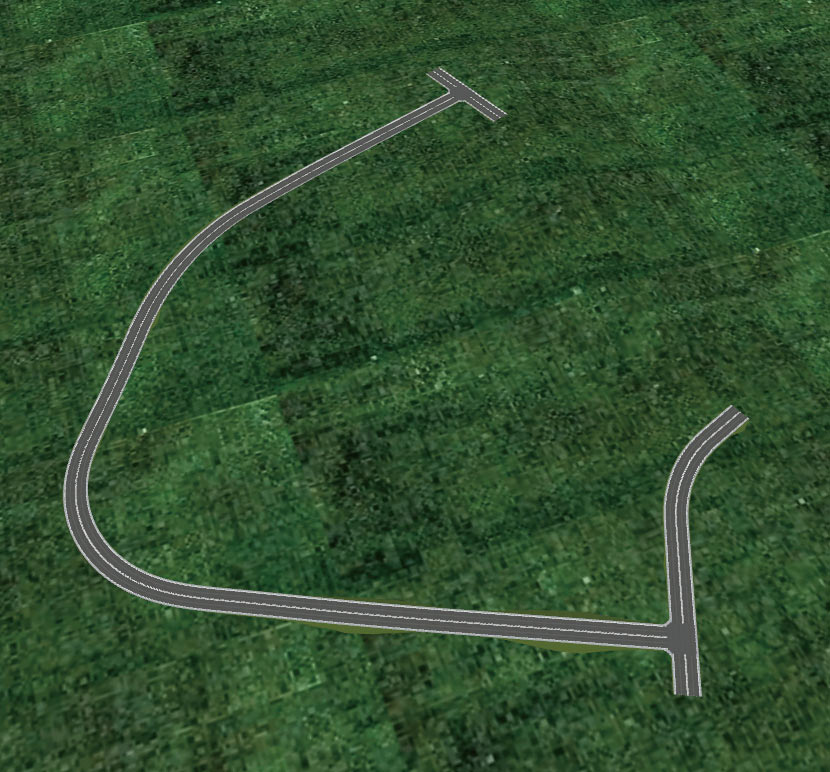
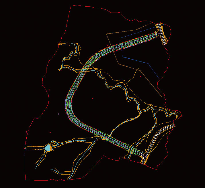
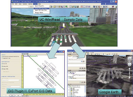
GIS application based on UC-win/Road
Satellite photo, terrain, road (Line), building (Polygon), flight route (Line,Spline), lake (Polygon)
Data integration with UC-1 Design Series (Japanese)
-
- Bridge Abutment Design
- Pier design 3D bar arrangement
- Rahmen type abutment 3D bar arrangement
- Plant foundation 3D bar arrangement
- BOX culvert 3D bar arrangement
- Retaining wall design 3D bar arrangement
- Manhole design 3D bar arrangement
- BOX culvert design 3D bar arrangement (earthquake-proof sewage system)
- Flexible structure sluiceway 3D bar arrangement
- Open channels 3D bar arrangement
- UC-Draw tools Retaining wall
- UC-Draw tools U-type wall
- UC-Draw tools Pier
- UC-Draw tools Abutment
- UC-Draw tools Box culvert
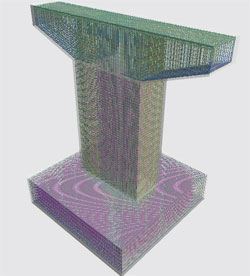
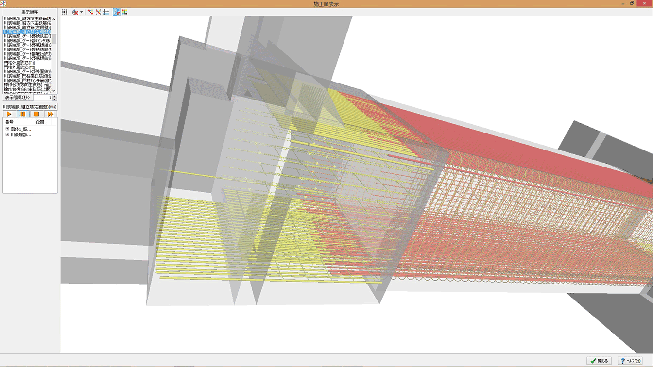
3D Bar Arrangement Simulation
●3D Bar Arrangement Simulation
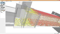
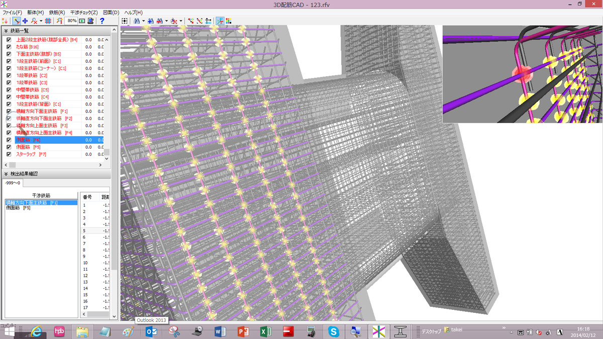
Bar arrangement drawings made by UC-1 series can be imported for 3D bar arrangement simulation
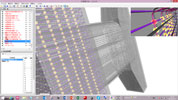
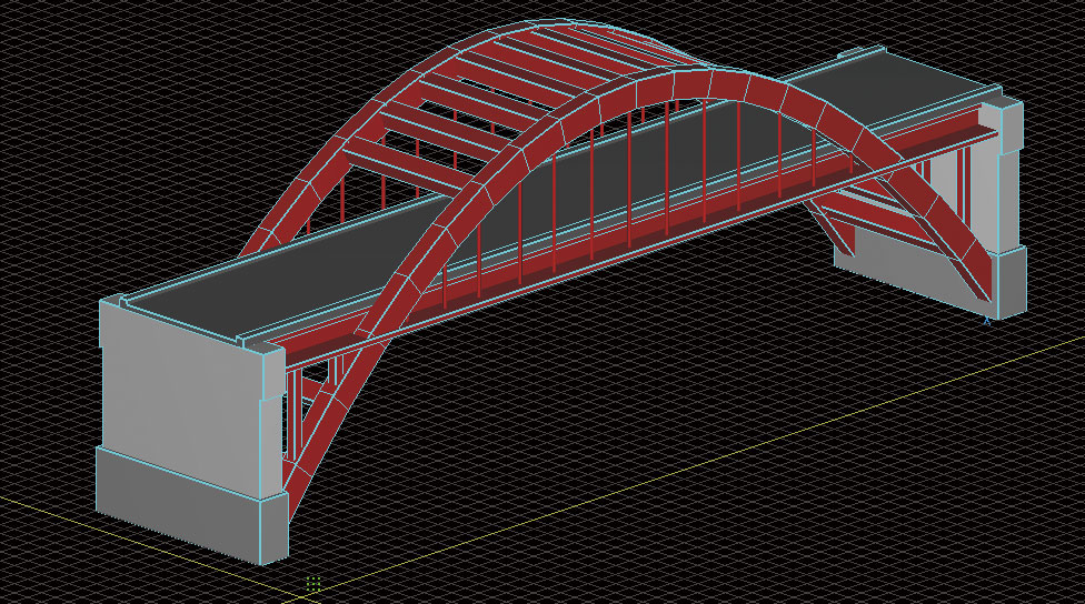
●3D bar arrangement CAD for SaaS
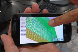
An advanced tool for construction sites supporting the simultaneous 3D/2D display of bar arrangement drawings on Android™ devices
●3DCADStudio®
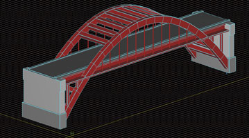
Data linkage of 3D modeling data and various programs is supported. DWG files can be imported and exported.

Data integration with road applications
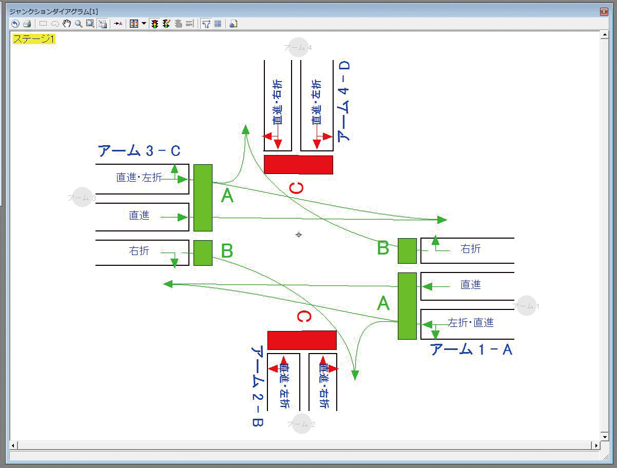
-
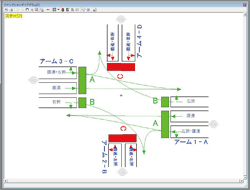
VR simulations cooperating with the traffic signal design software "OSCADY PRO".
■ TRL (http://www.trl.co.uk/)
In cooperation with UC-win/ Road, confirmation of analysis result of OSCADY PRO in VR space of 3D is possible.
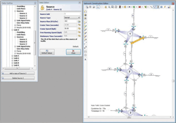
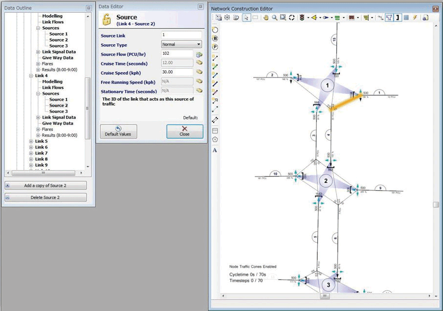
■ TRL (http://www.trl.co.uk/)
Specified format is provided from UC-win/Road. Vehicle position information is linked up with TRANSYT.
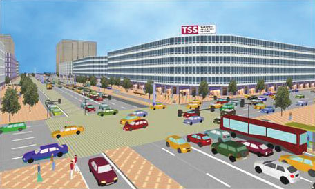
●Aimsun
■ TSS(http://www.aimsun.com/)
Public transportation, pedestrians / vehicles are reproduced by dynamic traffic assignment technique.
■ PTV (http://www.ptvag.com/)
The micro simulation system VISSIM and UC-win/Road are cooperated in mutual directions.
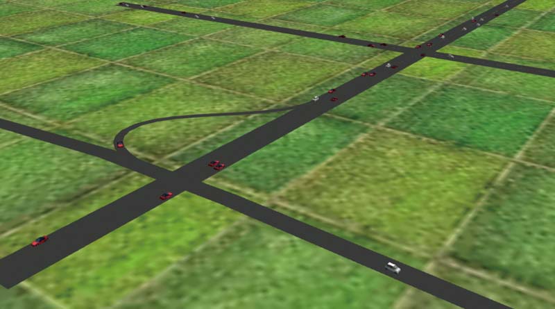
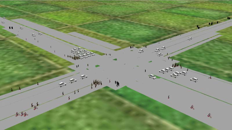
▲Road data of VISSIM

▲Result in UC-win/Road
Data integration with analysis software
-
- Visualization of the terrain model(importing shape file)
- Time-history of water level
- Time-history of flow vector
- Time-history of water level and pipe model
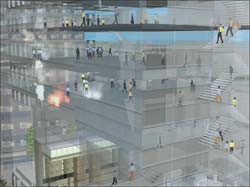
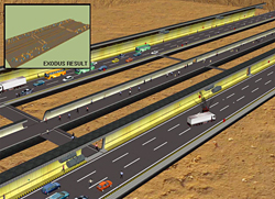
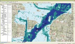
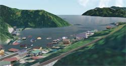
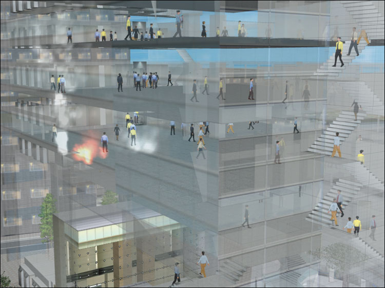
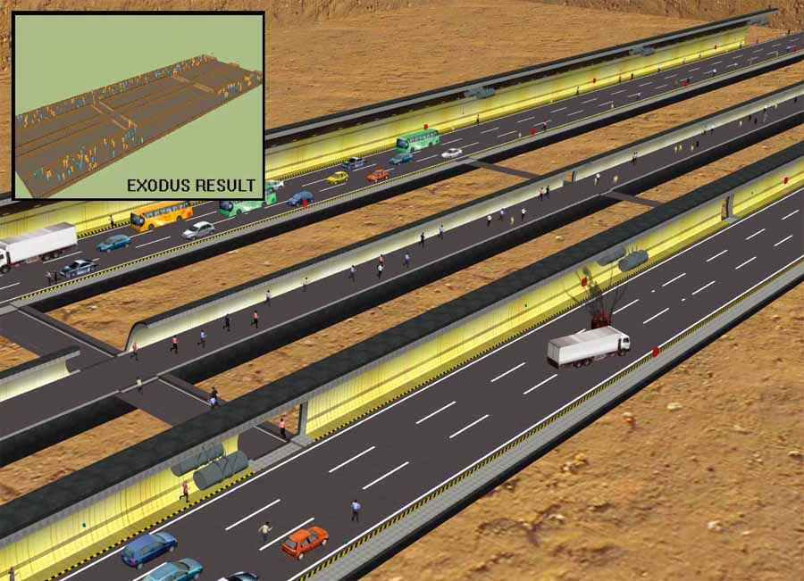
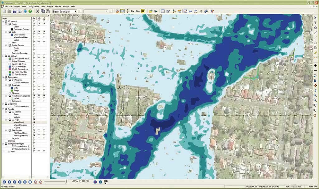
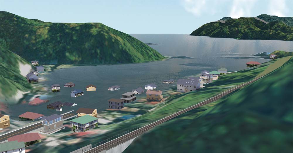
VR simulations realized by using the evacuation analysis software EXODUS and the flood analysis software xpswmm
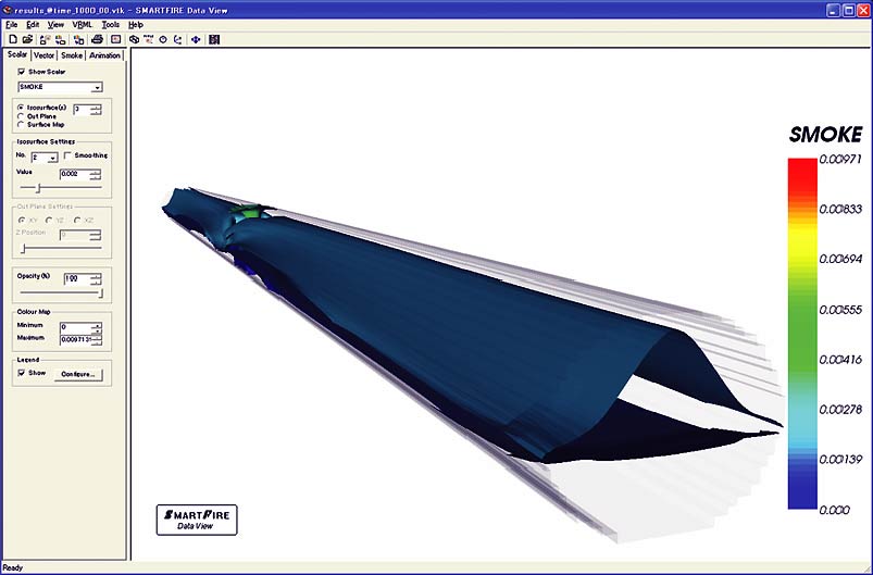
Data link of UC-win/Road and EXODUS (evacuation simulation) and SMARTFIRE (fire simulation) allows the viewing of the simulation result in 3D VR space.
Allows 3D view of the result of "xpswmm", flood analysis and inundation analysis
▲xpswmm
▲UC-win/Road for xpswmm
Product operation environment
3D data compatible format
-
3DStudio Object *.3ds
UC-win/Road can import 3D data in the 3DS, FBX, MD3, COLLADA, OBJ, etc. These file data can be created with the software below.
Reference:3D software list (Japanese)
Product operation environment
-
- A separately sold steering wheel with a brake pedal and an acceleration pedal, such as the Logitech Force GT, is required to enable the driving simulation.
- Please refer to the following page for UC-win/Road Driving Simulator:
https://www.forum8.co.jp/english/uc-win/road-drive-e.htm - Before using several screens, please confirm carefully that output ports on the graphic card are availabe. If it does not have enough output for the multiple screen system, add a graphic card to your PC.
- Confirm that your system satisfies the minimum requirements of the program before requesting the trial version or ordering the product license. However, you should run software on the system satisfying the recommended requirements.
- Please use the default screen design, font, and size. We recommend 20-inch or larger monitors.
Recommended system requirement for data creation OS Windows 10/ 11 (64bit OS) CPU intel® Core i5 / i7 / i9
4 core 8 threads or greater, Base clock 3.0 GHz or greaterMemory RAM greater than 32GB Hard Drive SSD drive
At least 60GB free space (At least 30GB free space is required for installing the VR-Design Studio including sample data and terrain data.) In addition, free space for saving downloaded models, textures, and AVI files is required.Video Card NVIDIA®️GeForce series, GTX1650 or greater, 4GB or more
UC-win/Road Video Card informationDisplay 1920x1080 or greater
Please use the 100% size setting for "Display" - "Change the size of text, apps, and other items".Sound card Anything Internet connection Mandatory
Internet access is required for schematic design and licence web authentication and for downloading data from Geographical Survey Institute map data and RoadDB.
Recommended system requirement for driving simulation OS Windows 10 / 11 (64bit OS) CPU intel® Core i5 / i7 / i9 4 core 8 threads or greater, Base clock 3.5GHz or greater Memory RAM greater than 16GB Hard drive SSD drive
At least 30GB free space (At least 10GB free space is required for installing the VR-Design Studio including sample data and terrain data.) In addition, free space for saving downloaded models, textures, and AVI files is required.Video card NVIDIA GeForce RTX 2070 or greater. 8GB video memory or greater
UC-win/Road Video Card informationDisplay 1920x1080 or greater
Please use the 100% size setting for "Display" - "Change the size of text, apps, and other items".Sound card Anything Internet connection Mandatory Steering controller Mandatory
Devices supporting DirectInput
Note:
Note
-
The Benchmark test result of UC-win/Road, UC-win/FRAME(3D)has been posted.
Our software performances, such as CPU, Memory, and Graphic adopter by a desktop PC and a notebook PC are available.Refer to:UC-win/Road Video Card Information
UC-win/Road Driving Simulator
-
- 3D driving environment can be freely created via UC-win/Road
- Standard plug-ins included
- Standard VR data is free and scenario customization is supported
- Various environments can be reproduced via visual option tools
- Reasonable pricing mass OEM production
- Supports high simulation needs by customization
完全な制御環境下で多様な走行環境を生成し、反復再現ができます。
近年、ドライブシミュレータは、車輌システム開発やITS交通システム研究、ドライバ、車、道路、交通との相互作用研究などに数多く適用されています。
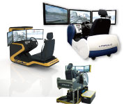
UC-win/Road Driving Simulator
-
- 3D driving environment can be freely created via UC-win/Road
- Standard plug-ins included
- Standard VR data is free and scenario customization is supported
- Various environments can be reproduced via visual option tools
- Reasonable pricing mass OEM production
- Supports high simulation needs by customization
4 wheels vehicle drive simulator packaging system
It allows you to create several driving situations and re-create it under complete control.
Recently Driving Simulator is widely used for vehicle system development or interaction research among drivers vehicles, road and traffic, on ITS traffic system research.
UC-win/Road Experience Simulator
-
6 axis motion unit/Subaru Driving Simulator
This simulator is fully integrated with force feedback steering mechanisms, which grant users a realistic experience, as if driving an actual vehicle. It also allows you to simulate driving environments in accordance with the rapidly improved car safety technology of ITS technologies (crash avoidance, decreased impact, etc.)
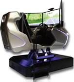

PLATEAU Driving SimulatorNEW!
-
Achieving zero accidents and resolve workforce shortages
Traffic and human flow data are reproduced on a digital twin using 3D city models.
More practical safe‑driving training can be conducted in an environment that accurately reflects the actual routes used by logistics operators.> > Details
■Selection
Area / Four vehicle types by industry / Veteran or beginner driver
■Training
Experience scenarios that reflect a variety of everyday situations.
■Assessment / Management
Playback by third-party assessment and review / Training records
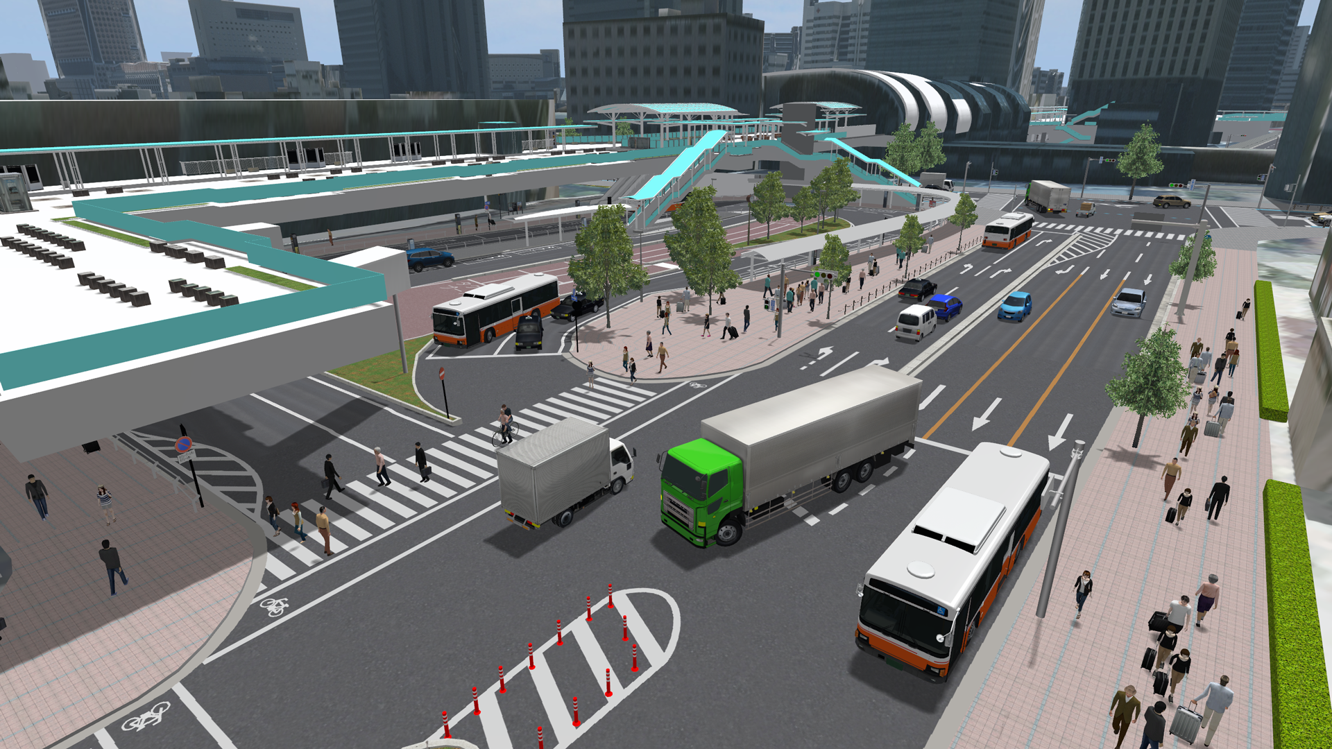
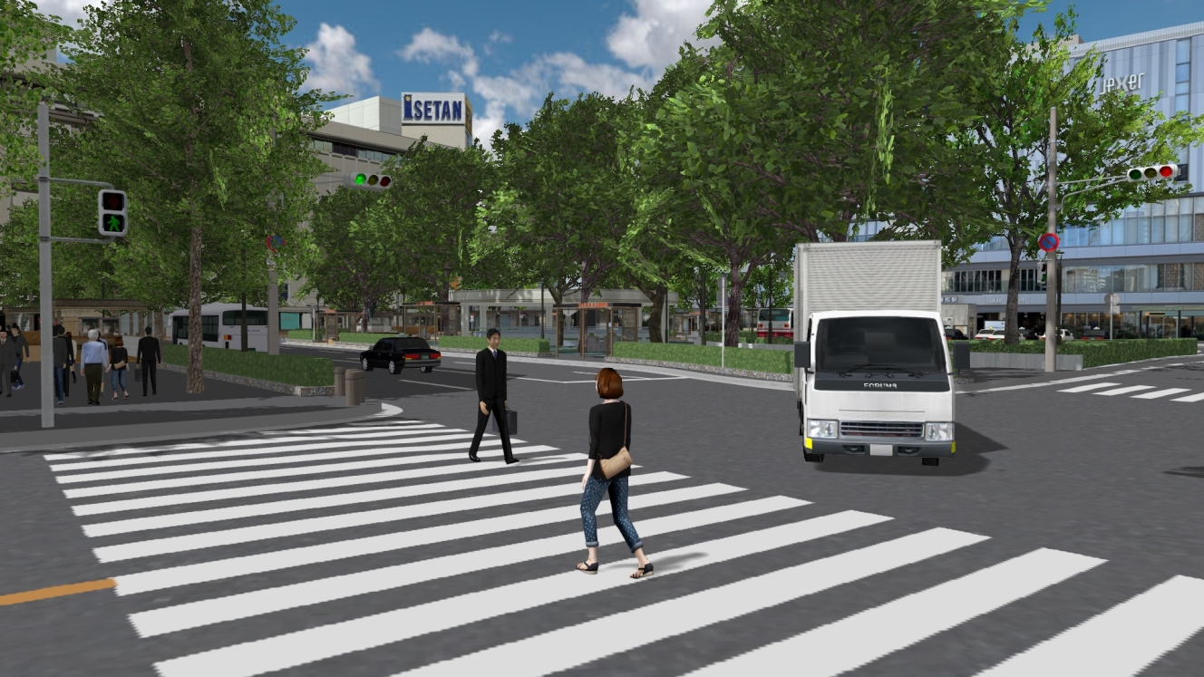
▲Streets and terrain are accurately reproduced using PLATEAU 3D city models, enabling training along realistic driving routes.
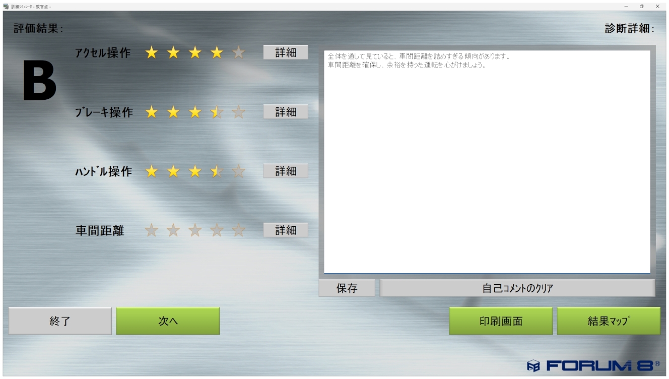
▲Scoring-based objective evaluation
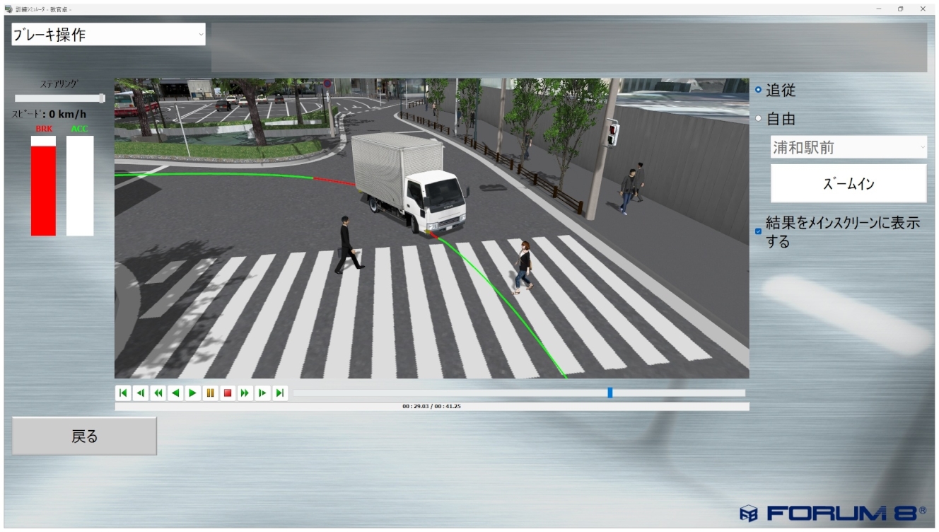
▲Review using a replay function
UC-win/Road Safe Driving Simulator
-
■Certified training drills (1st grade driving license)
1. Lesson on hazard prediction 2. Lesson on driving on highway
3. Lesson on location- specific conditions 4. Lesson on sudden braking
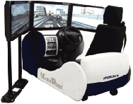
■System configuration
・PC for central control ・PCs for the driving simulators ・Printer
*All units are connected on a network
■ Diagnosis / Data collection program
・Diagnosis software ・Data collection software
UC-win/Road Wheelchair Simulator
-
Simulation using the cooperation of a wheelchair and UC-win/Road
The simulator is supposed to be a real wheelchair that does not move; a driver just sits in the simulator and drives the wheelchair within the VR environment projected through the monitor or Head Mounted Display (HMD). The simulator also has a function for evaluating driving skills.
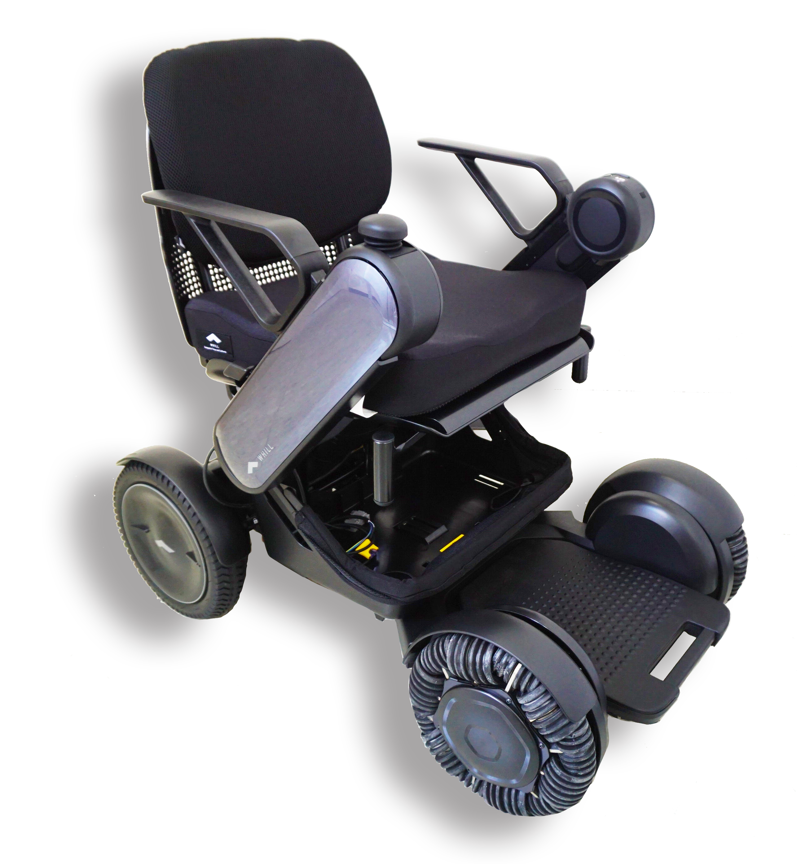
▲WHILL Model CR
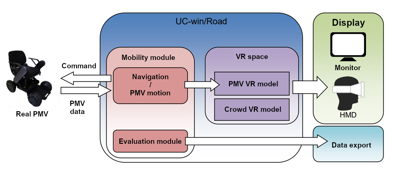
▲System overview
UC-win/Road Motorcycle Simulator
-
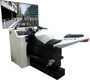
A full-fledged realistic motorcycle simulator packaged system
Motorcycle Simulator is a driving simulator cooperating with UC-win/Road VR driving simulation. Real motorcycle parts are used for the simulator, enabling the same operations as a real motorcycle, such as engine on/off, accelerator/brake, and lights. It also supports the steering reaction force by motor control, switching of the automatic motorcycle and manual motorcycle, and leaning of the simulator main body.
UC-win/Road Highway Driving Simulator
-
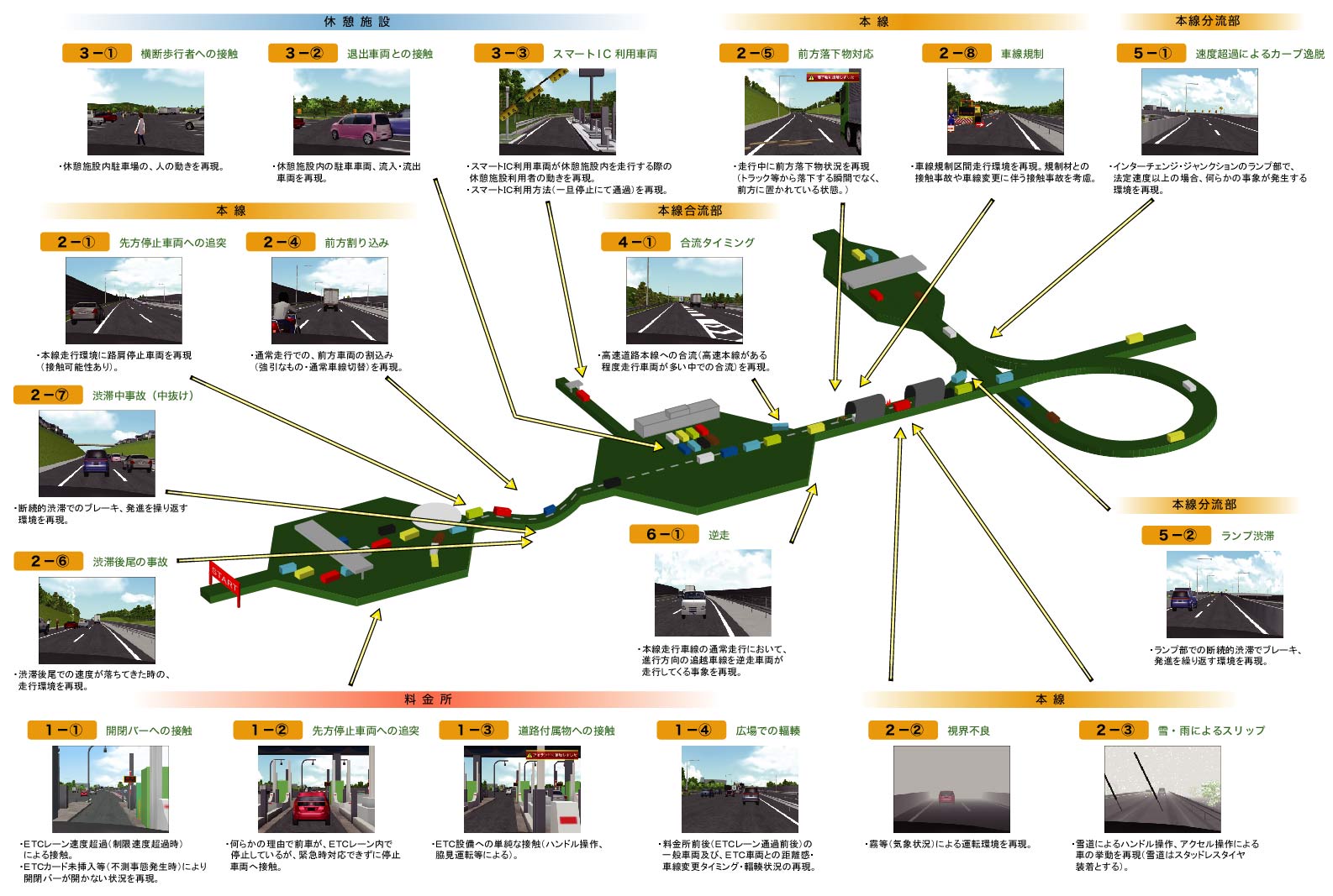
Potential hazards on highway can be replayed by the driving simulator
Based on Subaru automobile's technologies, the simulator body adopted 6 electric axis motion unit (patented) and automobile technologies from Subaru automobile. The use of actual car steering mechanism gives you a sense of realism whilst driving. With this experience simulator, you can experiences automobile safety technologies (collision avoidance, impact reduction, etc.), virtual traffic accidents, and new ITS technologies that have been rapidly developed in recent years.
Human-Vehicle-Traffic Flow Interoperable Driving Simulation System for Interactive Information Exchange
-
FORUM8 delivered research-purpose driving simulator referred to as "Human-Vehicle-Traffic Flow Interoperable Driving Simulation System for Interactive Information Exchange" to Kyushu University Graduate School of Integrated Frontier Sciences on March 22, 2012. The driving simulator will become the driving force for educational research activity on the next generation information / control devices in vehicles.
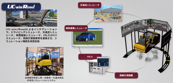
Research-purpose Driving Simulator has been delivered to Kyushu University
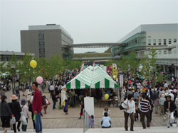
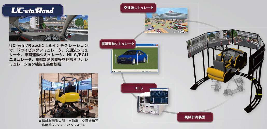
This driving simulation system was realized by linking the driving simulator, traffic flow simulator, vehicle dynamics simulator, HILS/ECU simulator, and eye tracking system and integrating them all into UC-win/Road. On May 13, 2012, the driving simulator was exhibited to the public for the first time since its delivery as one of the highlights of "Kyushu University Festival" held on Ito campus to commemorate the university's 100th anniversary. 106 people, many of them families, lined up to test drive the state-of-the-art simulator. The virtual test course is a 2 minute run that starts from a point in Taihaku-doori - a main street that runs across Fukuoka city - near FORUM8's Fukuoka Business Office and ends at Hakata station. Test drivers got very excited during the course of their drive as many of them acclaimed the driving simulator's cutting-edge technology by giving comments like "I'm really impressed with its ability to visualize so many aspects of the real world with high degree of realism. The image I'm seeing on screen is very pretty." FORUM8 delivered another research-oriented driving simulator (6DOF 5 Channel) on March 2012 to Faculty of Engineering, Kyoto University Graduate School of Engineering, Kyoto University.
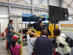
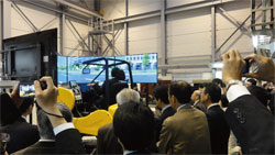
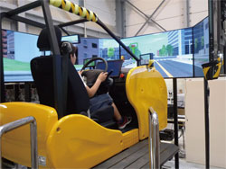
▲Unveiling ceremony of Human-Vehicle-Traffic Flow Interoperable Driving Simulation System for Interactive Information Exchange
(March 23, 2012 / venue : Kyushu University)
8DOF Traffic Safety Simulator
-
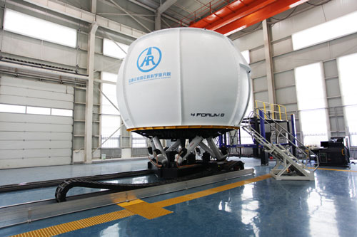
This is the high performance large-scale Driving Simulator based on Interactive 3D Virutal Reality Simulation & Modeling Software UC-win/Road.
This large scale Driving Simulator was planned and built for Rearch Institute of Highway Ministry of Transport in China (hereafter, RIOH) to be used for their traffic and safety research activity. RIOH outlined the specification of the Driving Simulator. In January 2009, FORUM8 received the order of the customized development of this Driving Simulator in the international tendor on its own., and in February 2014, the Final Acceptance Test was complete, marking the completion of the entire project.
Vehicular Dynamics Research & Evaluation System High-Precision Driving Simulator
-
Vehicular Dynamics Research & Evaluation System High-Precision Driving Simulator
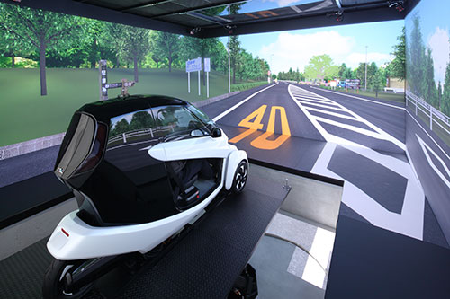
This simulator is the world-first 5-screen 3D stereoscopic VR driving simulator(*1) that incorporates numerous elements such as driving simulation, traffic simulation, and vehicle dynamics & performances, by building upon the the interactive 3D VR software UC-win/Road. FORUM8 has built and delivered this simulator inside the Nagoya University's National Innovation Complex (NIC) in June 2015.
>>Catalog of High Precision Driving Simulator for Vehicle Performance Analysis
(PDF、3,487KB)
●2016/02/16
BBC reported the World's First 4K Five-Screen 3D Stereoscopic Driving Simulator in Nagoya University's National Innovation Complex (NIC).
*1 As of June 2015, no large 5-screen CAVE simulator has been known to also include a real cockpit, hence this is currently a true "world-first" attempt.
UC-win/Road Customization System
-
- VR Motion Seat
- Lily Car
- Super-jumbo DS system : 6 axis + Yaw/X table and the entire circumference 8 projection / cluster composition
- UC-win/Road Bicycle simulator
- UC-win/Road Wheelchair simulator
- UC-win/Road Train simulator
- UC-win/Road Train signal visibility system
- UC-win/Road Ship handling simulator
- Man-machine interface
Develop high quality customized system flexibly by subdividing modules at low cost
●Easy to modify / add modules (driving simulation system)
Here are the developments cases in which we changed UC-win/Road vehicle dynamics model, customized user's hardware and log outputting of driving condition. It calculates the vehicle's movement by inputting the operation quantity of the pedal and the steering wheel from the usual game controler as an existing module structure (excluding added part on the right chart). Furthermore, it performs the calculation of vehicle's acceleration and track by an independent module. We modified the existing module for "Calculation of vehicle's acceleration". By doing so, customization of engine dynamic model of vehicles is made possible. Also by the modification of module for "Calculation of vehicle's track", we could fit the need of the road surface and the tire's adherence model. By the addition of "analog pedal device input" module and "pedal operation input switch" module, we could ensure the coexistence of the game controler and the other hardware, and accept the analog device. Finally, by adding module for "log acquistion and log saving", you can now obtain and output information regarding drive simulator.
The use of upgraded function and new feature function being developed in VR-Studio®
●Development of a new module / using in advance a function of product under development
In case we want to achieve a new function by customization, we develop the basic technique in a unique way, and continue on to design and develop in a way that would provide the most of the what the new function of the package has to offer. A function that runs scenario which can make the driving simulation improve significantly has been developed further by making use of know-how built up through customization and it will loaded as a new function to the next version. By the scenario function, it can put event in motion, elicit response from the drivers, and develop the stories of various driving. Also as for a newest technology of computer raphics, we adopt Shaders language for the next product, VR-Studio, and develop the texture processing of geography and the advanced expression of source of light.
The fulfillment of advanced simulation by the cooperation with hardware
●UC-win/Road Drive Simulator / Motion Platform
It is possible to customize UC-win/Road Drive Simulator(DS) which is a representative of cooperation with hardware.
"Motion platform" is has a maximum of 6 degrees of freedom, serving as a very realistic system that can provide maximum amount of feel of driving. Past developmental achievements in terms of DS include DS for car research, development of safe system, training simulator, simulator for publication, and train simulator. In the conbination with hardware, it can cover various simulation needs because it doesn't only make use of the features of real-time 3D VR which is essencial in cooperation with software but also it's the system which can perform the flexible drawing up of 3D space, modification and controling scenario and event.
FORUM8 Parking Solution
-
- Mobile application for searching and reserving parking lots on mobile phones and tablets
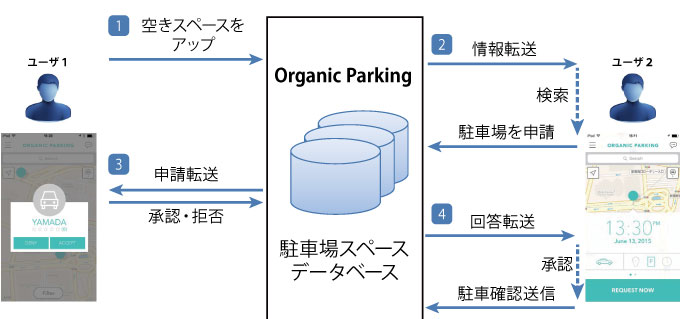
- Providers send information of parking lot or a place where to park a car, and a person who wants to use the parking space reserves via the system.
- The reason why it is named as Organic is that it promotes the community creation and the networking and cooperation between humans in addition to the environmental aspect that it avoids congestions and traffic jams and reduces emission.
- We are developing this service not only for reserving parking space but for getting a spot at events like fireworks event and cherry blossom viewing.
- Basic function: Empty spaces are displayed on the map in real time. Paid parking lot, parking space on streets, and vacant space in private property are supported.
- Vacant information is updated by users. When drivers finish to use the parking space, they connect to the service and send information of empty space to pass it on to other users searching parking space.
Parking Solution
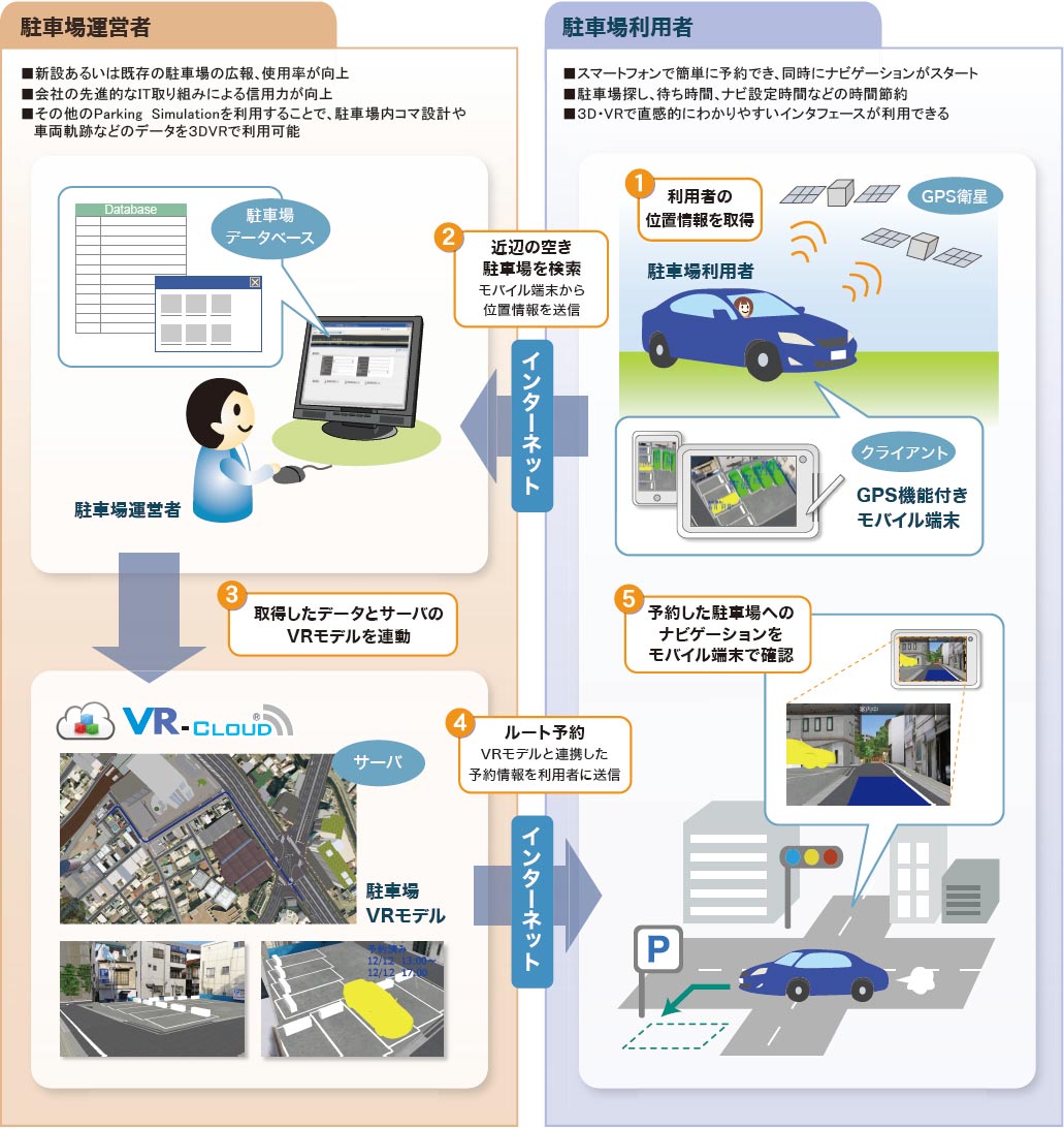
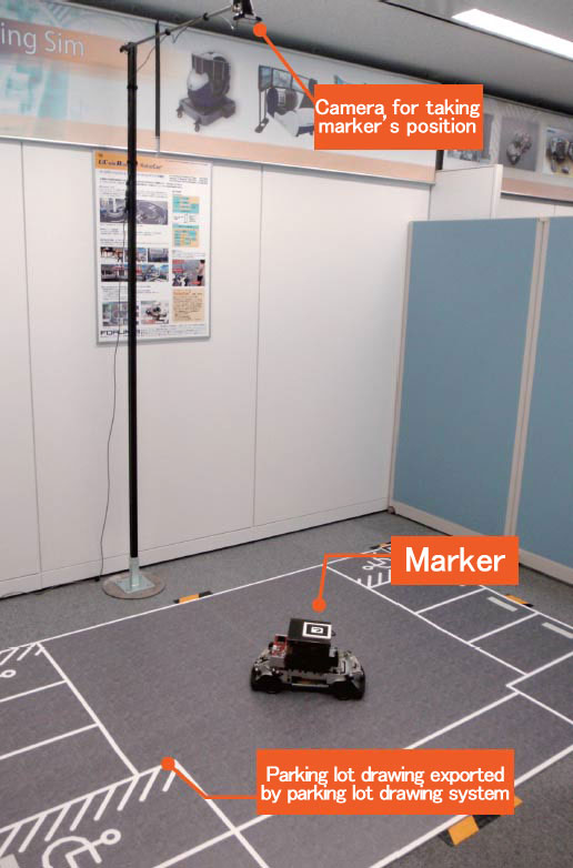
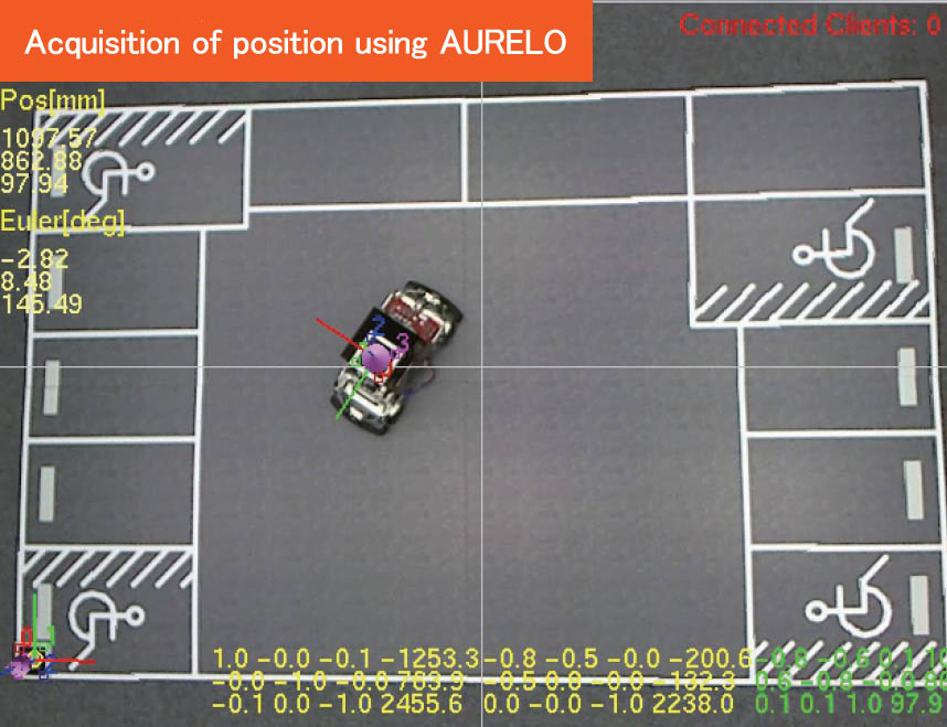
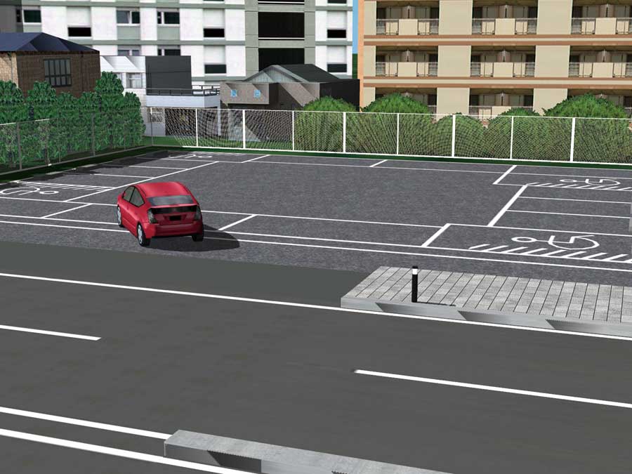
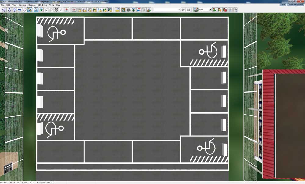
With the cooperation between the vehicle trajectory / parking lot CAD and UC-win/Road, we provide integrated solutions such as a searching and navigation system for empty spaces in the parking lot by using VR-Cloud®, autonomatic parking system by the synchronization with Robo Car® in addition to the creation of the parking model and its 3D VR simulation made from the drawing information.
●Organic Parking
This system was developed by Organic Parking in the US, aiming at a more eco friendly society with less congestions by reducing the time to seek for the parking space.
This service is patented in the US and is internationally patent-pending. FORUM8 has obtained the exclusive development right in Japan, and started to customize it.
UC-win/Road Vehicle trajectory / Parking lot CAD Automatic parking system
-
- Vehicle trajectory drawing system
This allows the user to calculate and draw the trajectory of vehicles based on the figurative theories of "Style of right angle turning trajectory drawing of semi-trailer and full-trailer (JASO ZOO6-92), Society of automotive engineers of JAPAN, INC." etc. Driving simulation on visualized routes and existing routes and drawing vehicle trajectory can be conducted efficiently. - Parking drawing system
This is a CAD system which designs parking lots based on the parking standards with the figurative theories of "Standard Parking Regulations", "Road Design Standards" etc. (Drawing plan view). It allows the user to export the constructed parking drawing to CAD data which can be used in our "Vehicle Trajectory Drawing System". - UC-win/Road RoboCar® Auto parking plugin
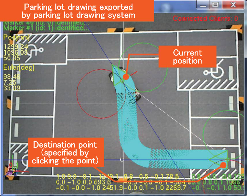
This system allow for the automatic operation of a steering wheel at the time of parking based on the information from a camera or ultrasonic sensor by linkage between UC-win/Road and RoboCar®. Parking can be conducted automatically by the driver simply pressing the button outside the car.
The vehicle trajectory drawing/ Parking design/ Automatic parking system
3DVR simulation is achieved by using the drawing information and by linking the creation of the trajectory mapping and the creation and design of the parking lot with UC-win/Road.
In addition, an automatic parking system is available through the synchronizing of the VR model and RoboCar®
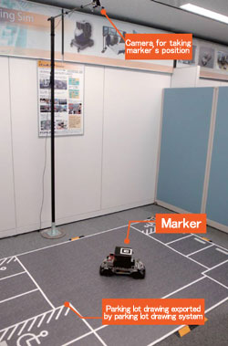
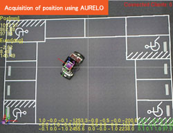

▲Automatic parking simulation of RoboCar® by using AURELO

▲Automatic parking can be checked in UC-win/Road
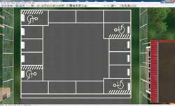
▲VR parking lot. View from any camera position you like
- Vehicle trajectory drawing system
FORUM8 Robotics
-
- Close visual inspection of concrete bridges
- Close visual inspection of floor board
The most advanced solution technology using robots
Fusion of car robotics platform and virtual reality
With UC-win/Road, you can create a vast virtual reality environment in a short time in easy workflow and operations. The linkage with RoboCar® can be applied to simulators in the mixed reality in addition to in VR, and it is expected to be used for a variety of simulators.
■What is RoboCar®
VR simulation system can be used to control 1/10 electric car scale model on model road. This can be performed by integrating "UC-win/Road", which is the virtual reality soft with well-developed driving simulation function and "Robo car", which is the car robotics platform mounted robot technology. This system allows users to create precision space images, many different styles of traffic environment and scenarios by using virtual space in VR, and experiment with them.
■Linkage between UC-win/Road and RoboCar®
In UC-win/Road, you can set precise space rendering and a variety of traffic environments and scenarios, and travel in the virtual space. RoboCar® is a one-tenth scale model of the actual car and runs in the real space. Combination of these characteristics enables the simulation in the mixed reality, which is not possible in the virtual space.
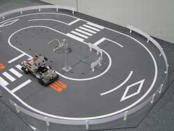
▲Creating the driving environments
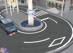
▲Running in VR space
●Mind&VR UC-win/Road for MindWave Mobile
Drive simulation in UC-win/Road with the brain-measuring interface MindWave Mobile
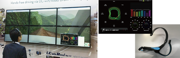
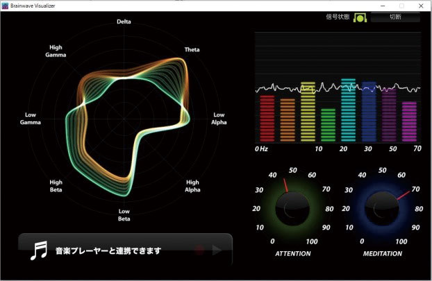
MindWave Mobile developed by NeuroSky is a wireless stereo head device equipped with a brainwave sensor. It measures the brainwave of the wearing person that is sorted by differences of frequency like alpha and beta, and converts it to the psychological state such as degree of concentration and relax via the original algorithm. By using MindWave Mobile plug-in and cooperating with VR data, users can perform operations and simulations using the acquired data. In the drive simulation below, speed of the vehicle is controlled according to the driver's degree of concentration. If the driver concentrates by staring at a point on the screen, the vehicle accelerates, and it decelerates if the driver gets distracted.
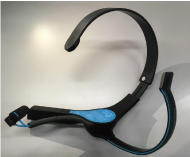
▲MindWave Mobile(Neurosky)
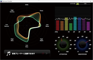
▲"Brainwave visualizer" (Neurosky)
■Case of use
UC-win/Road MindWave Mobile Plug-in
Driving by brainwave is possible when you start the drive simulation with MindWave Mobile wearing.
Acceleration and brake can be controlled by brainwave.
F1 race
Formula One (F1) racing is one of the study cases of EEG technology use. We loaded two MindSet units in real-time (@60Hz) and developed the interface that can extruct the meditation coefficient and the attention coefficient.
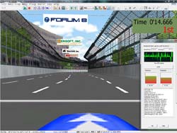
▲Phoenix F1 circuit
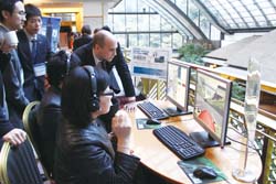
▲Appreciated as the system on display because of its game element
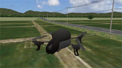
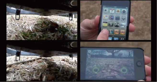
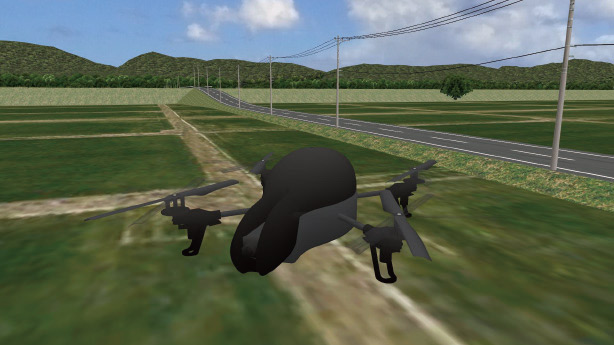
●Autonomous flight UAV
Autonomous flight monitoring system
■Operation by mouse or keyboard. Wireless data communication via Wi-Fi.
■The computer in the UAV automatically controls the balance and easily enables the advanced movement of the UAV such as up and down, forward and backward, and left and right.
■Images can be monitored through a front camera or high-speed camera and recorded with FLY-DV camera in detail.
■Measures the position of AR.Drone by GPS
■9DOF IMU (Inertial Measurement Unit) measures the acceleration, gyro, and earth magnetism, and confirms the direction of AR.Drone.
■It avoids the collision by using the infrared distance measuring sensor.
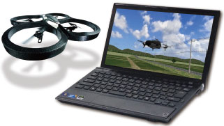
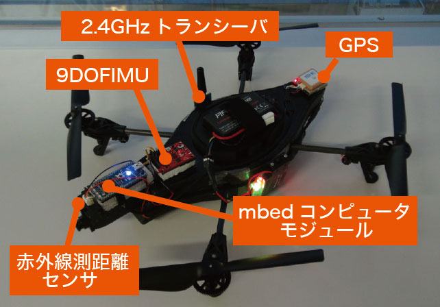
▲AGUL customization

▲AGUL test flight
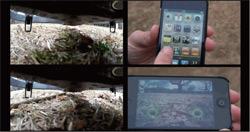
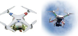
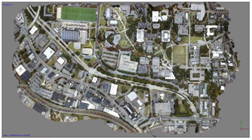
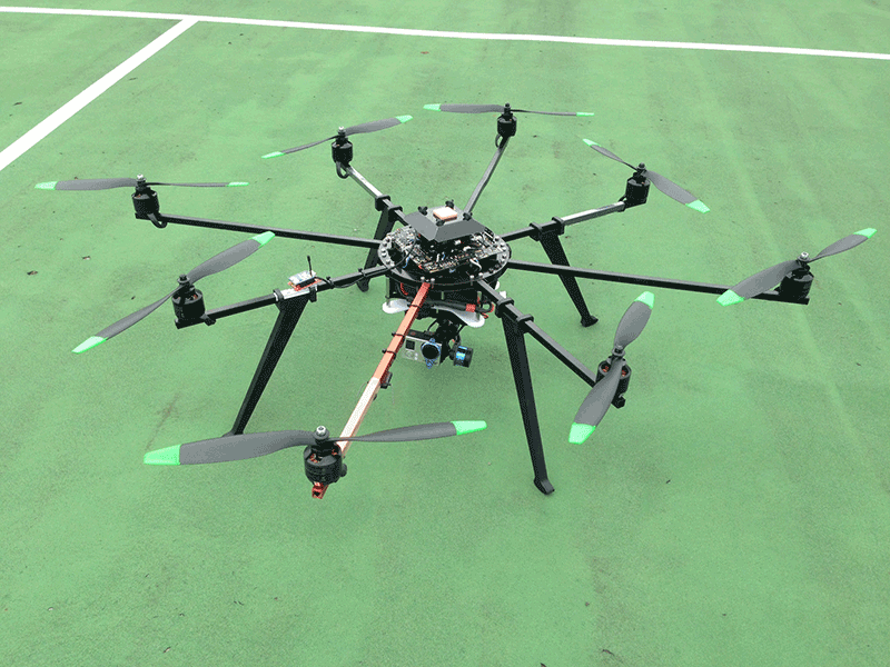
Micro Aerial Pilotless Scanning System (MAPs)
Mapping of a large area through the use of a pilotless unmanned aerial vehicle (Drone).
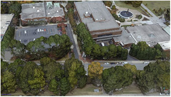
"System based on Autonomous UAV and 3D VR for Inspection and Assessment of Structures" in the field of 'bridge maintenance and management'
Adopted items
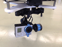
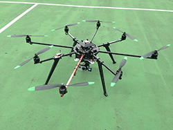
▲Customized autonomous flying robot
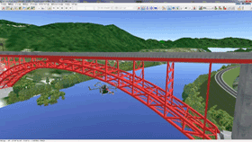
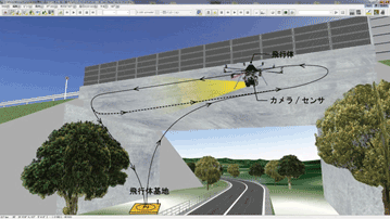
▲Linking 3DVR and autonomous flying robot
Handless driving simulation by infrared depth sensor
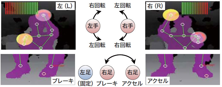
This system allows you to operate driving within UC-win/Road by the movement of both hands like operating the steering wheel in front of the Kinect™.
The position information of the both hands of a driver detected by the Kinect™ is converted to steering wheel, acceleration and brake of a car.
Imaging of vehicle control and driving operation by the infrared depth sensor
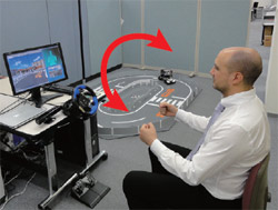
▲Steering operation (right-turning / left-turning)
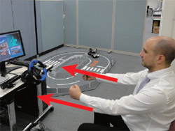
▲Acceleration operation
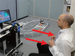
▲Brake operation
●Technologies used for UC-win/Road Air Driving
Fine and precise driving operation without control devices
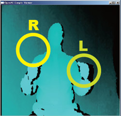
Recognition of skeleton
It extracts the same object from the distance information detected by the infrared depth sensor and identifies human characteristics. When the object person takes a specific pose, it does a calibration and recognizes the skeleton structure.
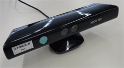
▲Kinect(TM) sensor
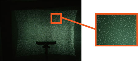
▲Pattern of the infrared laser
Detection of steering angle and steering direction
The right and left direction of the steering wheel and its steering angle are detected as an analog value from the positional relationship betweeen the user's right and left fist. How much the steering wheel is turned is indicated by a row of bars that change color from green to red. The bigger the steering angle, the more red the bar will be.
Distingishing accelerator from brake Accelerator
This is detected as an analog value from the amount of pressure the driver exerts on the accelerator pedal.
●Acceleration: The stack of bars will increase in the upward direction.
●Brake: The stack of bars will increase in the downward direction.
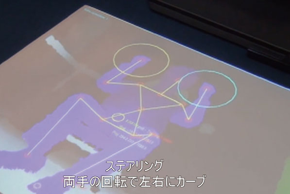
▲Travel in a straight line

▲Right turn: As you steer to the right,
the red bars will increase in the right direction.
●Multi-Cluster Digital Signage System with infrared depth sensor
The interactive digital signage system uses a 6K display on multi screens as well as the infrared depth sensor.
Intuitive operation using gestures and motions is possible.
This system can be interactively operated using the function of gesture interface and motion capture. Xtion PRO is used for the infrared depth sensor. The signage is operated interactively compared to the previous digital display. We also provide this service and various products such as real time VR simulation using the multi cluster system and UC-win/Road, CG rendering using the high-performance computer etc.
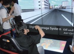
▲6K Digital Signage AirDriving (TOKYO GAME SHOW 2011)
▲AirDriving interface

New Solution Service "High-performance computing on cloud service"
Service of large-scaled analysis, simulation, CG rendering with the advanced calculation feature of high performance computing
■ UC-win/Road・CG movie service
High-definition movie files generated by POV-Ray is a feature of FORUM8' "High-performance computing on cloud services CG movie service". The high-definition movie file can be provided by use of a supercomputer. Since the movie files are generated by POV-Ray, their script files can be edited using an editor etc. after the movie files are exported to UC-win/Road.
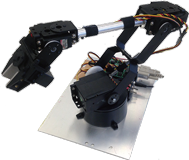
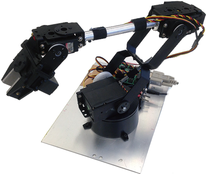
●UC-win/Road for Robot arm
Robot arms in virtual space and in real space move in conjunction with each other.
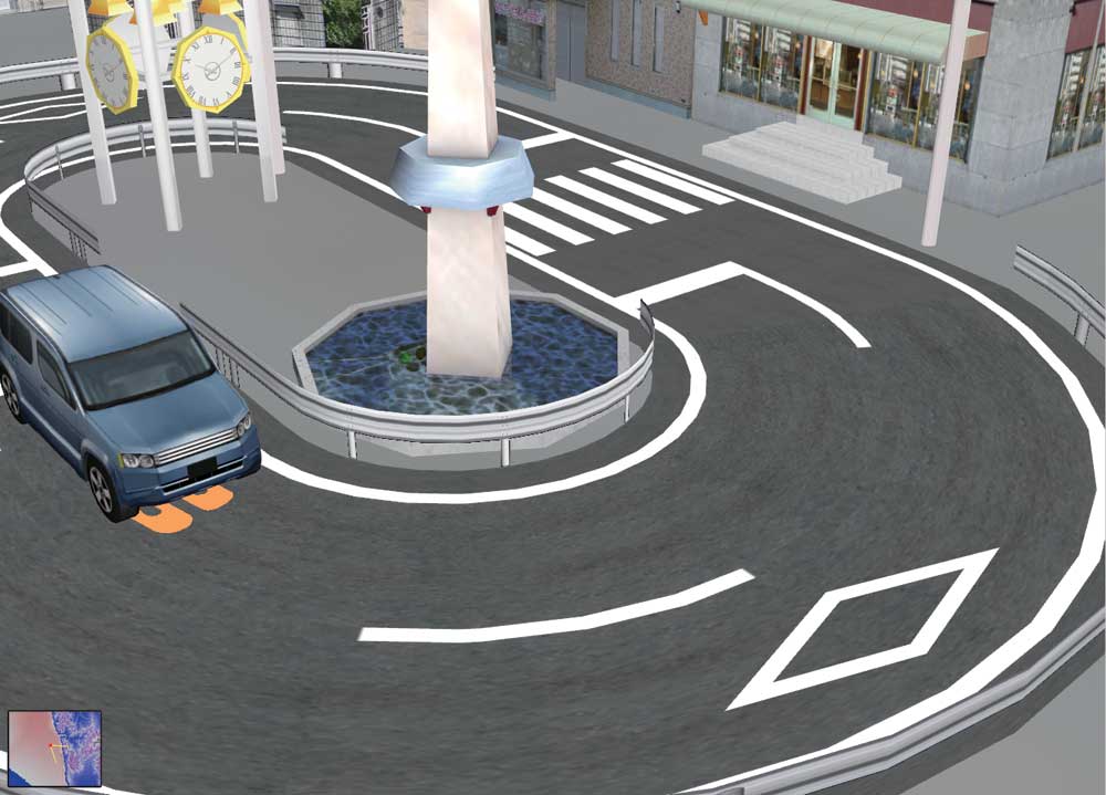
Autonomous car system via a scale model robotic car linked with VR
The Lily Car is a scale model robotic car, which purpose is to emulate on a small scale the behavior of actual cars and help the development of robotic cars.
The cars run autonomously on a test course, with several predefined paths. At any time, the user can switch the control mode between the manual or autonomous mode. The PC control interface connects to the Aurelo system to get the position and orientation of each car and sends the proper commands to the cars to make them follow the selected path.
System configration of Lily Car
- Chassis of a 1/10 RC car - Driving motor - Steering motor
- Infrared distance sensors for collision detection - An AR marker for the car tracking
- A wireless module to allow communication and control from a remote PC
- A main controller to manage the whole system





MR/AR
-
- With UC-win/Road, real-time simulation information can be used with 3D Stereo.
- Does not require polarized glasses. Depending on physical model size, many can be used as 'kiosks' with varying information strong visual impact with moving data.
●MR : Mixed Reality ●AR : Augmented Reality
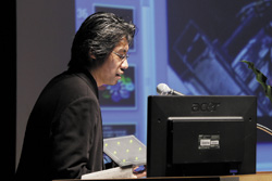
Shibuya cloud model and interactive device / Development of Linking System for VR and Interactive Devices
Mr. Taro Narahara (Graduate School in Harvard University, USA)
Mr. Narahara mentioned a project in which he introduced actions captured from real people into motions of figures, and represented more realistic figures on UC-win/Road.
In addition, he explained the mechanism that enabled real-time interaction by linking simulation and UC-win/Road on a real time basis through joint development of plug-ins with FORUM8.
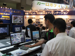
▲IVR exhibition 2010
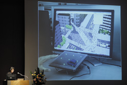
▲The presentation in the 3rd
International VR Symposium
3D Stereo System Naked eye 3D Stereo System
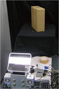
An example of system configuration
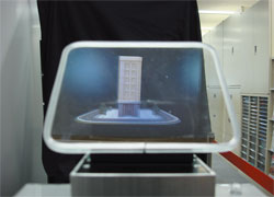
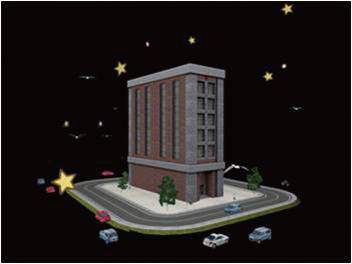
Glassless 3-dimensional image. Composition of a diorama and 3-dimensional image is displayed.
■What is 3D-B-Vision?
The 3D-B-Vision is a Mixed Reality, or more specifically, an Augmented Reality (AR) hardware system. With 3D-B-Vision, there is the added benefit of being able to project the digital information in the form of 3D-Stereoscopic CG.
The information can be displayed over architectural models or other physical objects.This glassless system is achieved by the use of two small projectors, placed eye-distance apart (for the 3D stereo capabilities). The participant looks through a transparent view window towards the physical object, and with the use of an overhead silver screen and lens filters, the 3D stereo image can be seen along with the physical setup. Cars, pedestrians, and other moving elements can be shown acting together for an effective presentation with the 3D-B-Vision's stereoscopic projection.
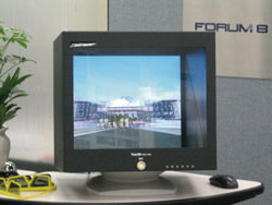
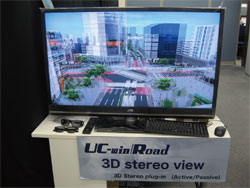
▲Normal view via 3D stereo
■Benefits
▲ Developed by: Ishikawa Kougaku Zoukei Laboratory Co.,Ltd. http://www.holoart.co.jp/
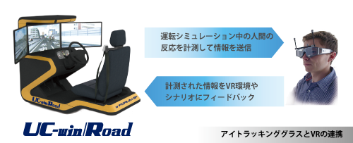
UC-win/Road Eye tracking system
Wearable device that measures information of humans line of sight and acquire its data.
Possible to connect to the drive simulation in VR space of UC-win/Road.
* Separate customization is required.
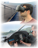
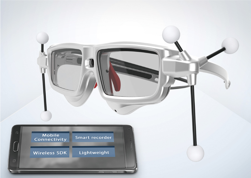
Eye Tracking Glasses Option
Eye tracking glasses that can "visualize" humans line of sight
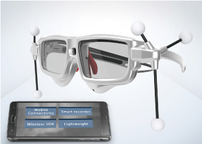
Sampling rate 60Hz or 30Hz Calibration 0, 1, 3 points Recording microphone ○ Scene camera (definition) 1280x960p @24 fps
960x720p @30 fpsRecording angle of the scene camera Horizontal: 80 degree
Vertical: 60 degreeContinuous recording time (PC) 2 hours (Galaxy) 2 hours Recording capacity (PC) 18 hours (Galaxy) 20 hours Weight (Glasses main unit) 47g Weight (Galaxy) 176g Size (Glasses main unit) 135 x 69 x 23 mm Precision of regard 0.5° Contents construction
・60Hz binocular Eye Tracking Glasses with HD scene camera
・Snap on frame for ETG (3D)
・Row data full access SDK
・Recording software iView license
・VRPN Server
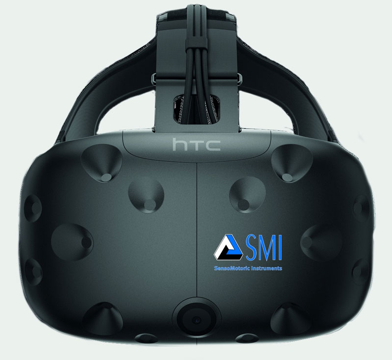
Eye Tracking HMD based on HTC Vive Option
Made by SMI and based on HTC Vive. Line of sight information is attached to the high-performance model of 250 Hz.
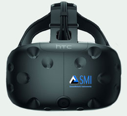
Eye tracking Tracking 250Hz (Both eyes) Tracking range Full visual field
(110 degree)Precision of regard 0.2 degree Calibration 1,3,5 point Measuring data Point of regard on display
(left, right, both eyes), gazeInterpupillary distance (IPD) Standard point of regard,
gaze tracking
HeadgearHardware Plug and play connection of HTC
Vive headset / Unecessary to
adjust before connection / USBHead unit Eye tracking
Module part: 55g
Operation deviceSystem requirement PC with HTC Vive activated OS Windows10 64bit Contents construction
・HTC Vive main unit / attachment
・Binocular Eye Tracking at 250 Hz (Embedded module)
・Row data full access SDK
・Plug-in for Unity, WorldViz Vizard, Unreal Engine
・Recording software iView license
・VRPN Server
* The specification above may be altered without notification for improvement.
Developed by SMI
HMD System / Head Mounted Display System
3D image output by Quest Rift
With extremely wide view angle. Head tracking by the internal sensor.
■What is Quest Rift?
A Head Mounted Display (HMD) developed and provided by Meta in the US at lower price than existing HMD. Head tracking by the internal sensor and 3D image output of wide view angle are available.
■Display
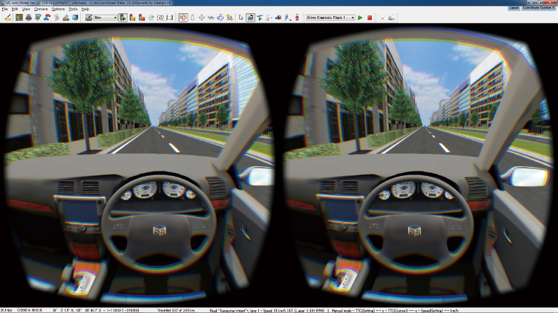
Quest Rift has an overwhelming wide field of view as a HMD. This is because that the fish-eye model screen shows wearers the flat liquid crystal display as if he/she is looking at a semi-hemisphere projector screen in front of him/her. Combination with stereoscopic view due to the difference of view between right and left improves the immersion feeling into the VR space. In addition, existing HMDs display normal images owing to spending much cost to the optical system in order to reduce the lens distortion to the minimum, whereas the Quest Rift renders source images so that wearers can see good images when seeing through the distorted lens.
Quest Rift Plug-in creates a stereoscopic 3D image with lens barrel distortion and tracks the camera view within UC-win/Road in line with the user's head movement using the sensor data.
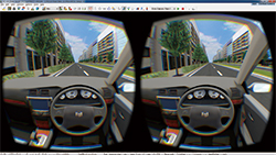
▲Stereo view
UC-win/Road physical model VR system
-
Simulation / presentation system in combination with physical model and VR
"UC-win/Road Physical Model and VR System" was developed based on the idea and cooperation of Associate Professor Tomohiro Fukuda of Osaka University, a member of W16. Thanks to the technology of providing a combined operation environment of physical model and VR system, it is a new type simulation/presentation tool combing the features of both environments. The system allows you to present information effectively and efficiently to the people concerned with different background and varying knowledge levels.
Details >> UC-win/Road physical model and VR system(Up&Coming '11 Early Spring issue)
Technical Support : Associate Professor Tomohiro Fukuda, Graduate School of Engineering, Osaka Univeristy
■ Tool for examination with advantages of both physical and VR model
Advantage of VR : VR is highly flexible and expressive, and allows various considerations such as reproduction of traffic flow or changed weather conditions, which is impossible through a physical model.
Advantage of physical model : Physical model is more intuitive way to understand the overview of planning including the distance and size. Physical model allows various people to examine from the arbitrary viewpoints at the same time, understanding the whole city model simultaneously and touching the model directly.
■ Deciding the viewpoint under consideration in a physical model and displaying it in a VR model
The planning can be studied by easy and intuitive operation in comparison with VR only. In "UC-win/Road Physical Model and VR System", you can move in the VR space and make changes in the view direction by indicating the view points to examine with laser pointer on the model. The system consists of model, web camera, laser pointer, VR software "UC-win/Road", and display unit to view the VR display space. As a whole, the system consists of two functions: detecting laser pointer operation, passing detected information to UC-win/Road and representing it in VR space.
■ Physical model VR system "Nakameguro Safety and Security Map" exhibited in the Showroom
The physical model VR system of "Nakameguro Safety and Security map" is exhibited in the showroom of FORUM8 Tokyo head office. Please come and visit us.
■ Proposal and quotation of system
FORUM8 will offer the proposal and quotation of "UC-win/Road support system" based on the requirements of each customer. With UC-win/Road Support system, 3D VR simulation data can be created based on their needs. The created VR data can be modeled by exporting VR data to the physical model using 3D printer in a short time with "3D physical model service" so that the physical modeled VR system can be effectively structured.
Quotation example: "Nakameguro Safety and Security Map" Physical model VR system The proposal system with the physical model in Nakameguro. The maintenance condition of infrastructure in the basement and the inside space of building can be checked as "Area safety and security map" where the physical model and VR are integrated, and it can be used. for the consensus formation in the city re-development project.
■VR data creation : About JPY3,200,000 ■3D physical model creation : About JPY3,800,000
* Including the cost of ARToolKit license, Web camera, laser pointer, desktop computer, 42inch display, UC-win/Road Advanced x1 license, customization charge of UC-win/Road, and technical fee
Total From JPY15,400,000
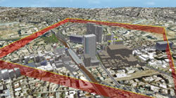
▲ "Nakameguro safety
and security map"
Overview of VR model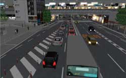
▲The area in front of
Nakameguro station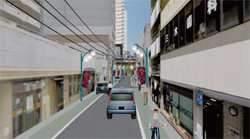
▲Meguro Ginza
Shopping Avenue
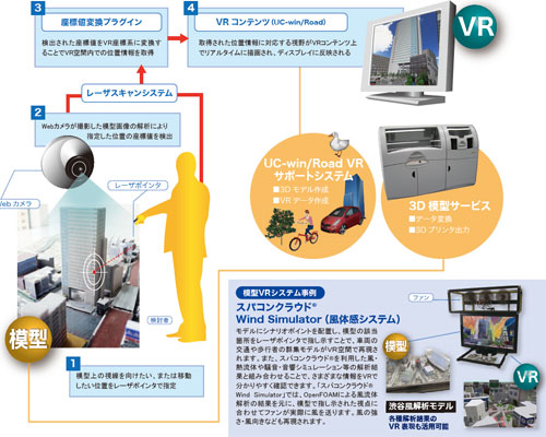
▲System configuration
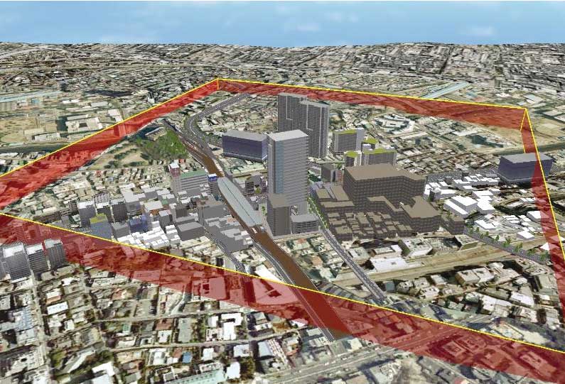
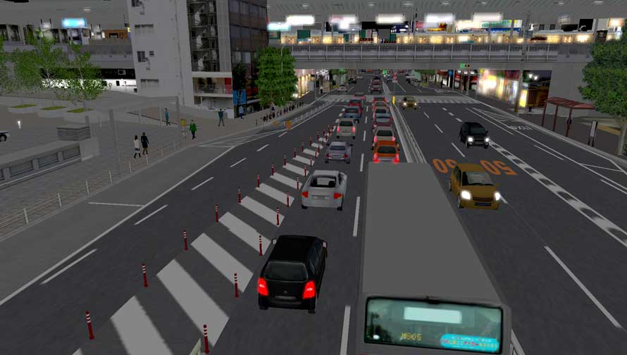
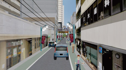
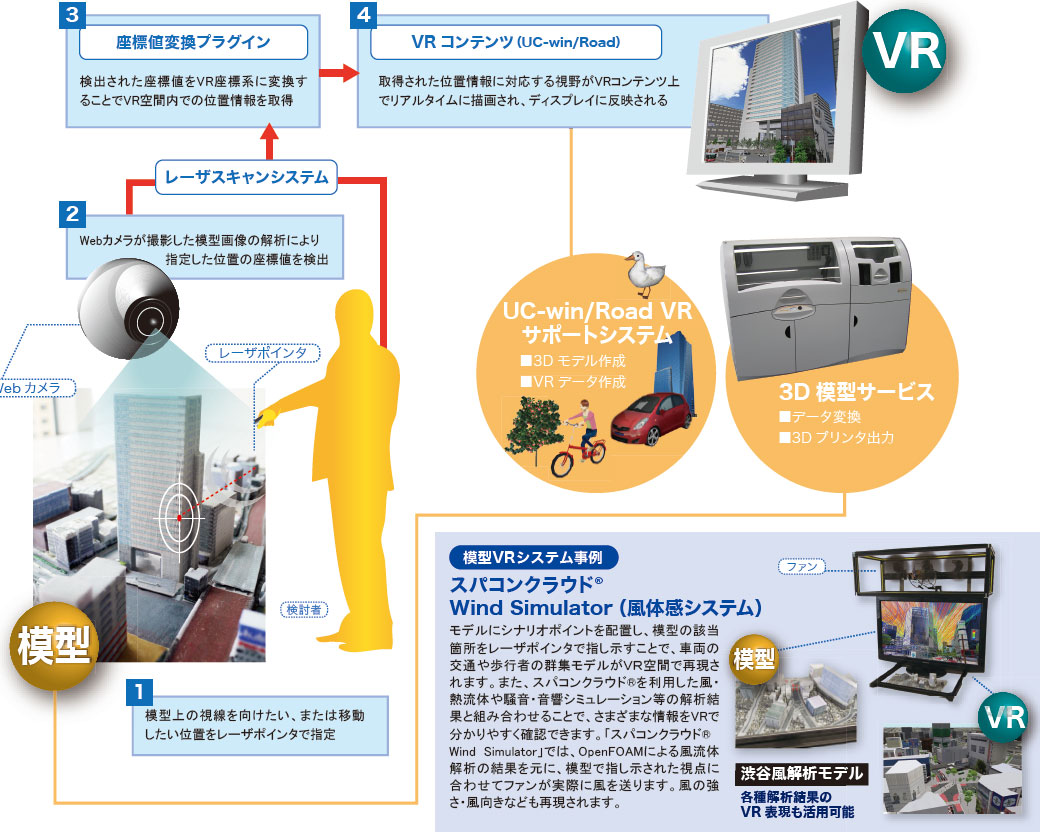
3D Projection Mapping
-
- Location : A relatively dark place outdoor and relatively easy to install and do projection mapping without affect traffic.
- Target structure : A tower shaped building with simple geometry
- Building size : W10m x D6m x H20m
- Building's material : Bricks (brown / opaque)
- Number of location from which image shall be projected : 2 at most
- Projection distance : approx. 15m (A:near) approx. 40m (B:far)
- Work is approx. 3 min. long and includes image and sound effects (user defined, MA)
- Rental period of device generating image and sound effect : 3 days (1 day for preparation, 2 days at the event)
- Includes onsite testing and progress management
- Includes equipment transportation, setup and adjustment
- Operator and image / sound effect engineer available
- Transport / travel / accommodation fee required for areas other than the Kanto region (Tokyo and the surrounding prefectures)
- Cost of stand and crane rental not included.
- A stereoscopic display device exceeding a hologram and enhancing mapping around a 3D model <Press release issued on March 30, 2016 (Japanese)>
- Projection mapping table <Up&Coming No.108 '15 New Year issue (Japanese)>
The practice of projection an image on a physical structure using 3DVR technology and contents
FORUM8 offers the state-of-the-art spatial visualization technology that uses 3DVR data and image, namely the "3D Projection Mapping".
Cooperation : State of the Art Technologies in Expression Association
3D Projection Mapping (in Japanese) <Up&Coming No.96 '12 Spring issue>
3D Projection Mapping (Part2, in Japanese) <Up&Coming No.97 '12 Summer issue>
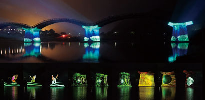
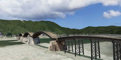
▲ Projection mapping on Kintai-kyo bridge "Space-time bridge" (2015.5.30)
【YouTube URL】http://youtu.be/kJ3rKsV3iQ0
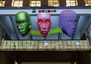
▲Projection mapping at Shibaura
Institute of Technology (2015.09.10)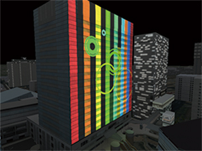
▲VR data to check image of projection mapping
Projection solution that uses VR
By running a projection simulation via UC-win/Road and 3D Engineering Service, image can be confirmed by either lookign at the VR model or by exporting the model to a physical miniature model prior to the actual event. The solution is an ideal tool for verification of contents, discussion with stakeholders, explanation and advertising to the customer, and of course advertisements before and after the projection event.
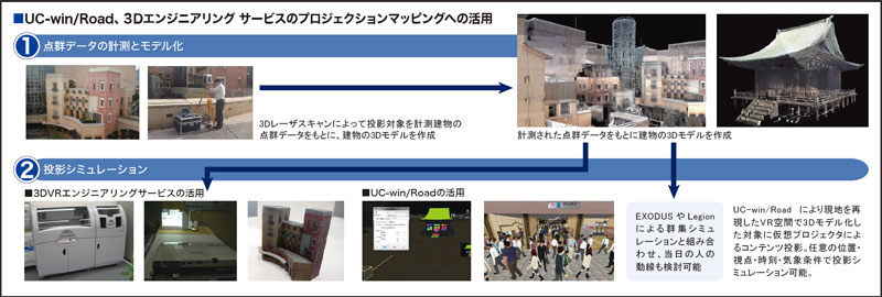
An example of model projection plan
An example of a plan
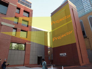
▲2 projectors used
List of model projection plans (2D, 3D contents)
*Cost of sound effects : The cost of devices that generate sound effects and the contents of sound effects, a total of approximately USD10,000 is included.
*Includes 3D animation content and sound effects
Equipments 1 projector 2 projectors Projector projecting
a 10000 lumen image
USD51,500 USD71,000 Projector projecting
a 20000 lumen imageUSD57,500 USD82,000
Projection Mapping Table
Design simulation system by all around mapping using UC-win/Road and a 3D model
Ex: Projection of grid texture and real car texture
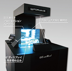
▲Grid texture
▲Real car texture
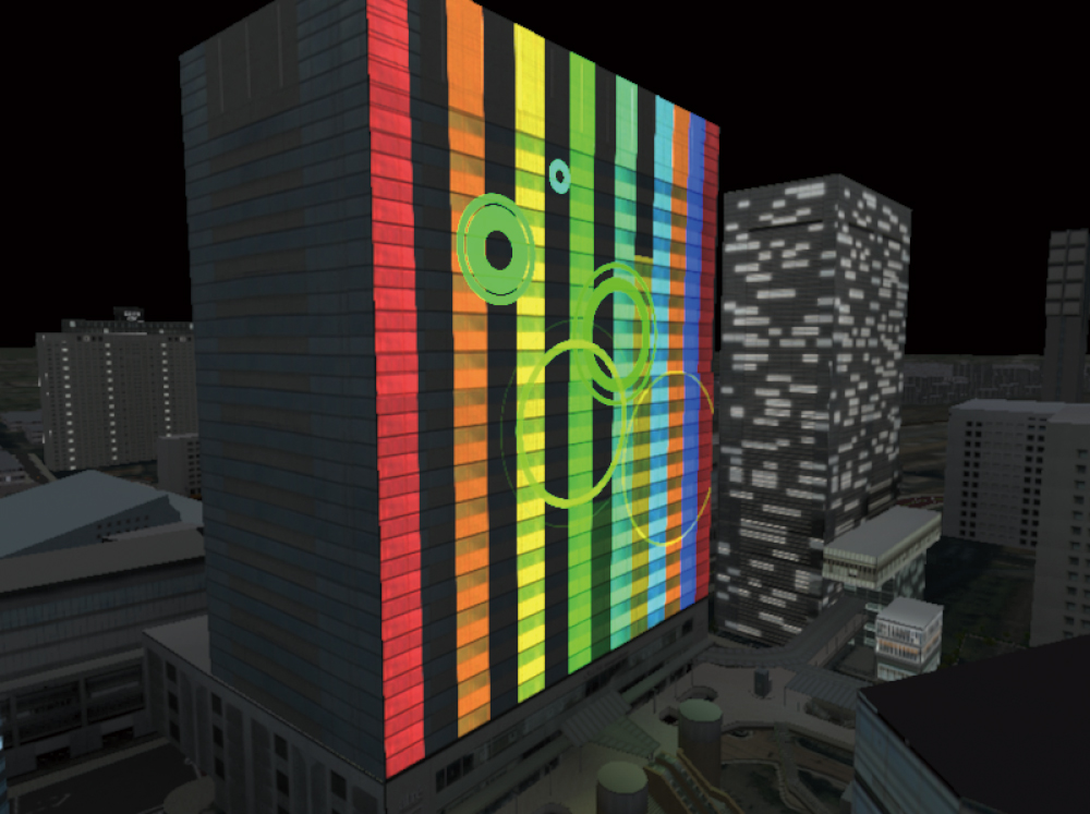

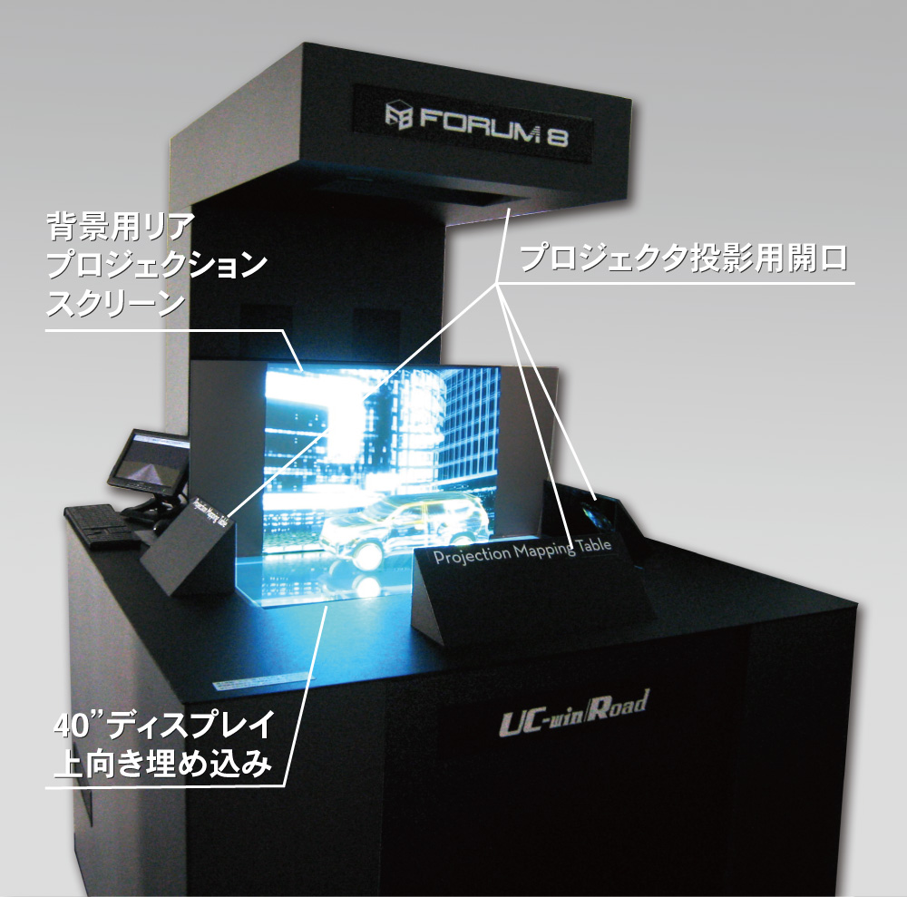


IM&VR
-
Integrated Solution via BIM/CIM&VR
BIM / CIM is a model that integrates various information in building and civil engineering, and a method of creating, managing and utilizing such information. It is capable of designing and representing various information within the entire life cycle of a building including basic and detailed drawing, rendering image, presentation image, bill of quantities, etc.
As for VR and UC-win/Road, we offer "IM & VR solution" in cooperation with simulations such as landscape, sunshine, traffic, wind, noise, immersion / tsunami, evacuation, energy analysis, and construction plan in front loading (consensus formation and planning).
Details >>IM&VR
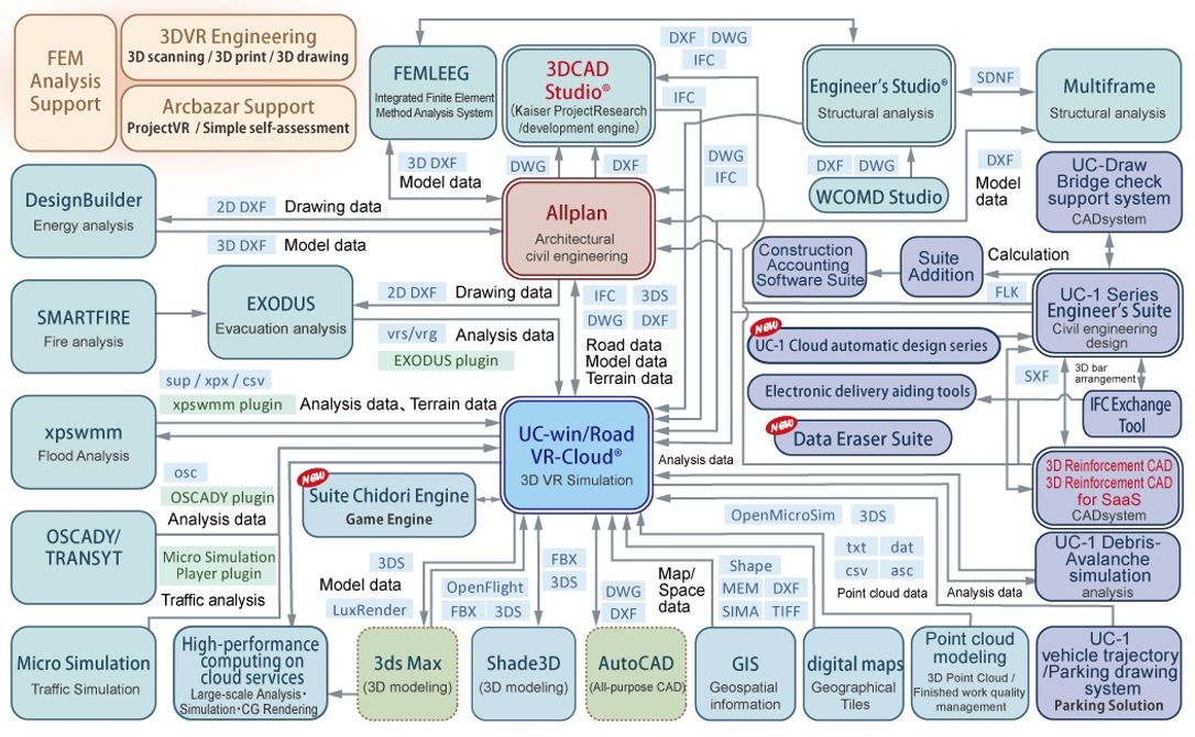
FORUM8 Surveying Solution
-
Integrated solutions that involve GIS / 3D Laser scanning / 3D Survey & Civil Engineering CAD
We offer integrated surveying solutions such as point cloud measurement by 3D laser scanner and VR modeling of point cloud data via UC-win/Road; data exchange between 3D survey CAD and civil infrastructure design CAD, and VR system; and building a system that links GIS to VR technology.
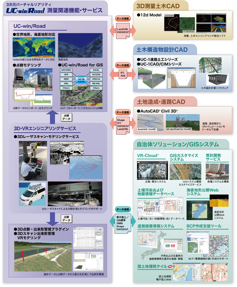
Price of Subscription Service Contract
Price of Subscription Service Contract
-
■Support information
-Software upgrade -Technical inquiry (Email, Tel)
-Download service -Maintenance and update notifications via email* We are sequentially making a transition from the maintenance-support service to [Subscription Service] from April 1, 2016 in order to enhance support for diverse product usage and to reduce license management cost.
■Subscription Contract
Product NamePrice of first yearPrice of subsequent yearsUC-win/Road Ver.19 (Ultimate)USD19,200USD9,600UC-win/Road Ver.19 (Driving Sim)USD12,800USD6,400UC-win/Road Ver.19 (Advanced)USD9,700USD4,850UC-win/Road Ver.19 (Standard)USD6,300USD3,150UC-win/Road Ver.19 (CIM Lite)USD5,280USD2,640UC-win/Road Ver.19 (Multi User Client Version)USD1,180USD590UC-win/Road Ver.19 (Presentation Version)USD660USD330UC-win/Road Ver.19 (Cluster Client Version)USD660USD330■Subscription Floating Contract
Paying 40% of the product price allows anyone to use the products on any PC anywhere in the world.
The price from the second year onward will be the price listed above for the second and subsequent years of the subscription, plus an additional 40%.Product NamePricePrice of subsequent yearsSubscription FloatingUltimateUSD7,680USD13,440Driving SimUSD5,120USD8,960AdvancedUSD3,880USD6,790StandardUSD2,520USD4,410CIM LiteUSD2,112USD3,696Multi User Client VersionUSD472USD826Presentation VersionUSD264USD462Cluster Client VersionUSD264USD462■Pricing structure revision regarding changes to subscription rates
From July 1, 2025, the pricing structure for products equipped with F8-AI® Support was revised to 50% of the product price.
■Subscription Contract Update Price for Users of UC-win/Road Ver.18
For the initial contract renewal only, it will require both the price difference between Ver.18 and Ver.19 of the main product and the new subscription contract described above.
* For contracts that include product options, the total charge will be calculated by adding the main product subscription cost and the product option subscription cost.[Ultimate]
Feature Enhanced Cost: USD2,000
Feature Enhanced Cost for Floating License: USD2,800[Driving Sim]
Feature Enhanced Cost: USD1,800
Feature Enhanced Cost for Floating License: USD2,520[Advanced]
Feature Enhanced Cost: USD900
Feature Enhanced Cost for Floating License: USD1,260[Standard]
Feature Enhanced Cost: USD300
Feature Enhanced Cost for Floating License: USD420[CIM Lite]
Feature Enhanced Cost: USD480
Feature Enhanced Cost for Floating License: USD420[Multi User Client Version]
Feature Enhanced Cost: USD100
Feature Enhanced Cost for Floating License: USD140[Presentation Version]
Feature Enhanced Cost: USD60
Feature Enhanced Cost for Floating License: USD84[Cluster Client Version]
Feature Enhanced Cost: USD60
Feature Enhanced Cost for Floating License: USD84
Upgrade
Upgrade Price
-
Product NameObject ProductPrice/CategoryUC-win/Road Ver.19 UltimateUC-win/Road Ver.19 Driving SimUSD7,680UpgradeUC-win/Road Ver.19 UltimateUC-win/Road Ver.19 AdvancedUSD11,400UpgradeUC-win/Road Ver.19 UltimateUC-win/Road Ver.19 StandardUSD15,480UpgradeUC-win/Road Ver.19 UltimateUC-win/Road Ver.19 CIM LiteUSD16,704UpgradeUC-win/Road Ver.19 Driving SimUC-win/Road Ver.19 AdvancedUSD3,720UpgradeUC-win/Road Ver.19 Driving SimUC-win/Road Ver.19 StandardUSD7,800UpgradeUC-win/Road Ver.19 Driving SimUC-win/Road Ver.19 CIM LiteUSD9,024UpgradeUC-win/Road Ver.19 AdvancedUC-win/Road Ver.19 StandardUSD4,080UpgradeUC-win/Road Ver.19 AdvancedUC-win/Road Ver.19 CIM LiteUSD5,304UpgradeUC-win/Road Ver.19 StandardUC-win/Road Ver.19 CIM LiteUSD1,224Upgrade
Price of Rental License / Floating License
■Rental license : Short term licenses available at a low price
■Rental floating license : After web activation, anyone can use the products on any PC anywhere in the world.
■Rental access : You can increase the number of licenses you own and use these additional licenses for a specific period of time (1 month to 3 month) at your discretion. We will later send you an invoice based on your usage log. The advance application is 15% off of the regular rental license price. Please place an order from User information page.
*Rental / Floating Licenses were introuduced on September 2007 to enhance user experience and convenience of our products.
*Duration of Rental / Floating Licenses cannot be changed after starting these services. Re-application is required to extend the rental and floating license duration.
Rental license / Rental floating license
-
●Application software
■Rental license
Product Name2 month3 month6 monthUC-win/Road Ver.19 UltimateUSD8,640USD10,176USD12,480UC-win/Road Ver.19 Driving SimUSD8,760USD6,784USD8,320UC-win/Road Ver.19 AdvancedUSD4,365USD5,141USD6,305UC-win/Road Ver.19 StandardUSD2,835USD3,339USD4,095UC-win/Road Ver.19 CIM LiteUSD2,376USD2,798USD3,432UC-win/Road Ver.19
Multi User Client VersionUSD336USD396USD488UC-win/Road Ver.19
Cluster Client VersionUSD336USD396USD488■Rental Floating License
Product Name2 month3 month6 monthUC-win/Road Ver.19 UltimateUSD14,400USD17,088USD21,120UC-win/Road Ver.19 Driving SimUSD9,600USD11,392USD14,080UC-win/Road Ver.19 AdvancedUSD7,275USD8,633USD10,670UC-win/Road Ver.19 StandardUSD4,725USD5,607USD6,930UC-win/Road Ver.19 CIM LiteUSD3,960USD4,699USD5,808UC-win/Road Ver.19
Multi User Client VersionUSD885USD1,050USD1,298UC-win/Road Ver.19
Presentation VersionUSD567USD673USD831UC-win/Road Ver.19
Cluster Client VersionUSD567USD673USD831
●Plug-in Options
■Rental license
Product Name2 month3 month6 monthUSD1,512USD1,780USD2,184USD1,512USD1,780USD2,184USD778USD916USD1,124USD1,512USD1,780USD2,184USD778USD916USD1,124USD1,512USD1,780USD2,184USD1,512USD1,780USD2,184VR-Cloud® Plugin (including a3S SDK server license)USD1,512USD1,780USD2,184(function of VR-Cloud® SDK) *requires VR-Cloud® PluginUSD1,512USD1,780USD2,184VR-Cloud® Collaboration Plugin
*requires VR-Cloud® PluginUSD2,475USD2,915USD3,575USD778USD916USD1,124USD382USD450USD555USD1,512USD1,780USD2,184USD1,278USD1,505USD1,846USD382USD450USD555USD531USD625USD767USD1,512USD1,780USD2,184USD1,512USD1,780USD2,184USD408USD480USD592USD408USD480USD592USD408USD480USD592USD382USD450USD555USD1,044USD1,229USD1,508USD408USD480USD592USD382USD450USD555USD1,512USD1,780USD2,184USD2,475USD2,915USD3,575USD382USD450USD555USD408USD480USD592USD285USD335USD415OpenDRIVE PluginUSD408USD480USD592CityGML PluginUSD408USD480USD592■Rental Floating License
Product Name2 month3 month6 monthUSD2,520USD2,990USD3,696USD2,520USD2,990USD3,696USD1,297USD1,539USD1,903USD2,520USD2,990USD3,696USD1,297USD1,539USD1,903USD2,520USD2,990USD3,696USD2,520USD2,990USD3,696VR-Cloud® Plugin (including a3S SDK server license)USD2,520USD2,990USD3,696(function of VR-Cloud® SDK *requires VR-Cloud® Plugin)USD2,520USD2,990USD3,696VR-Cloud® Collaboration Plugin *requires VR-Cloud® PluginUSD4,125USD4,895USD6,050USD1,297USD1,539USD1,903USD645USD765USD945USD2,520USD2,990USD3,696USD2,130USD2,527USD3,124USD645USD765USD945USD885USD1,050USD1,298USD2,520USD2,990USD3,696USD2,520USD2,990USD3,696USD688USD816USD1,008USD688USD816USD1,008USD688USD816USD1,008USD645USD765USD945USD1,740USD2,064USD2,552USD688USD816USD1,008USD645USD765USD945USD2,520USD2,990USD3,696USD4,125USD4,895USD6,050USD645USD765USD945USD688USD816USD1,008USD480USD570USD710OpenDRIVE PluginUSD688USD816USD1,008CityGML PluginUSD688USD816USD1,008
●Additional Options
■Rental license
Product Name2 month3 month6 monthUSD3,870USD4,558USD5,590USD3,600USD4,240USD5,200USD1,350USD1,590USD1,950USD1,350USD1,590USD1,950USD900USD1,060USD1,300USD1,512USD1,780USD2,184Simulation Real Time Link OptionUSD2,250USD2,650USD3,250HIL Link OptionUSD8,100USD9,540USD11,700USD1,512USD1,780USD2,184USD408USD480USD592USD1,512USD1,780USD2,184USD3,870USD4,558USD5,590USD1,422USD1,674USD2,054USD1,512USD1,780USD2,184USD1,044USD1,229USD1,508USD1,044USD1,229USD1,508USD1,350USD1,590USD1,950USD429USD514USD643USD510USD600USD740USD1,800USD2,120USD2,600Steering Torque Control OptionUSD4,050USD4,770USD5,850USD2,250USD2,650USD3,250Laser Sensor OptionUSD8,100USD9,540USD11,700USD1,350USD1,590USD1,950USD1,350USD1,590USD1,950USD3,600USD4,240USD5,200Camera Sensor Link OptionUSD9,000USD10,600USD13,000USD1,800USD2,120USD2,600USD1,350USD1,590USD1,950USD1,350USD1,590USD1,950USD1,350USD1,590USD1,950USD1,350USD1,590USD1,950USD1,800USD2,120USD2,600USD1,575USD1,855USD2,275USD1,350USD1,590USD1,950CAN Link OptionUSD4,050USD4,770USD5,850A/D Board Link OptionUSD8,100USD9,540USD11,700USD1,800USD2,120USD2,600USD1,350USD1,590USD1,950USD1,350USD1,590USD1,950USD1,350USD1,590USD1,950USD900USD1,060USD1,300USD1,800USD2,120USD2,600■Rental Floating license
Product Name2 month3 month6 monthUSD6,450USD7,654USD9,460USD6,000USD7,120USD8,800USD2,250USD2,670USD3,300USD2,250USD2,670USD3,300USD1,500USD1,780USD2,200USD2,520USD2,990USD3,696Simulation Real Time Link OptionUSD3,750USD4,450USD5,500HIL Link OptionUSD13,500USD16,020USD19,800USD2,520USD2,990USD3,696USD688USD816USD1,008USD2,520USD2,990USD3,696USD6,450USD7,654USD9,460USD2,370USD2,812USD3,476USD2,520USD2,990USD3,696USD1,740USD2,064USD2,552USD1,740USD2,064USD2,552USD2,250USD2,670USD3,300USD885USD1,050USD1,298USD860USD1,020USD1,260USD3,000USD3,560USD4,400Steering Torque Control OptionUSD6,750USD8,010USD9,900USD3,750USD4,450USD5,500Laser Sensor OptionUSD13,500USD16,020USD19,800USD2,250USD2,670USD3,300USD2,250USD2,670USD3,300USD6,000USD7,120USD8,800Camera Sensor Link OptionUSD15,000USD17,800USD22,000USD3,000USD3,560USD4,400USD2,250USD2,670USD3,300USD2,250USD2,670USD3,300USD2,250USD2,670USD3,300USD2,250USD2,670USD3,300USD3,000USD3,560USD4,400USD2,625USD3,115USD3,850USD2,250USD2,670USD3,300CAN Link OptionUSD6,750USD8,010USD9,900A/D Board Link OptionUSD13,500USD16,020USD19,800USD3,000USD3,560USD4,400USD2,250USD2,670USD3,300USD2,250USD2,670USD3,300USD2,250USD2,670USD3,300USD1,500USD1,780USD2,200USD3,000USD3,560USD4,400
●Related Products
■Rental license
Product Name2 month3 month6 monthUSD2,475USD2,915USD3,575USD1,512USD1,780USD2,184USD1,512USD1,780USD2,184USD275USD324USD399USD643USD757USD929■Rental Floating license
Product Name2 month3 month6 monthUSD4,126USD4,895USD6,050USD2,520USD2,990USD3,696USD2,520USD2,990USD3,696USD464USD550USD680USD1,072USD1,272USD1,573
Plugin List
Plugin List
-
Plugin NameUltimate USD19,200Driving Sim USD12,800Advanced USD9,700Standard USD6,300CIM Lite USD5,280Price
 ---USD3,360---USD3,360---USD1,730---USD3,360--USD1,730--USD3,360--USD3,360--USD800VR-Cloud® Plugin
(including a3S SDK server license)--USD3,360--USD3,360VR-Cloud® Collaboration Plugin
*requires VR-Cloud® Plugin--USD5,500---USD1,730---USD750---USD3,360---USD2,840---USD750---USD1,180---USD3,360---USD3,360-USD800DWG Tool Plugin
*requires Export Scene Plugin-USD800-USD800----USD750----USD2,320----USD750----USD3,360----USD5,500-USD750-USD800----USD500OpenDRIVE Plugin----USD800CityGML Plugin-USD800Welding Plugin----USD3,000Plugin NameUltimate USD19,200Driving Sim USD12,800Advanced USD9,700Standard USD6,300CIM Lite USD5,280Price
Additional plug-in options
Additional plug-in option
-
Additional Plug-in OptionPriceUSD8,600USD8,000USD3,000USD3,000USD2,000Remote Access plug-in optionUSD3,360Simulation Real Time Link OptionUSD5,000HIL Linkage option *4USD18,000USD3,360USD3,000USD4,000USD4,000USD800USD4,000USD4,000Steering Torque Control option *4USD9,000USD1,180USD8,600USD3,000USD3,000FOVE plug-in option (64bit only)USD3,000USD3,000USD3,000USD8,000Camera Sensor Link option *4USD20,000USD3,000CAN Signal Link option *4USD9,000A/D board link option *4USD18,000USD3,160USD2,320USD5,000Laser sensor option *4USD18,000USD3,360USD1,000USD2,320USD3,000USD3,500USD180/monthUSD3,360USD3,000USD3,000USD3,000USD2,000USD4,000Haptics plug-in optionUSD2,000
*4 Provided for only system development / *5 Configuration: 3 slave PCs & 1 server PC
Related Products
Related Products
-
Related ProductsPriceUSD5,500USD3,360USD780USD3,000USD540USD1,430Free of chargeUC-win/Road Video tutorial(Japanese, English, Korean, Chinese)USD300
Price of UC-win/Road Driving Simulator
Price of UC-win/Road Driving Simulator
-
UC-win/Road Driving Simulator Price of system (Packaging system)SpecificationsOrder quantity1 DS10 DS20 DSUC-win/Road-Drive Simulator
Basic configuration
・1/4 Cabin, Full Instrumentation
・3ch. 42” PDP monitor
・5.1ch Speaker, Body Sound
・CFLS Controller
・Active Steering WheelUSD67,100USD60,400USD50,400UC-win/Road Driving SimUSD12,100USD10,300USD8,400TotalUSD79,200USD70,700USD58,800*Options item1 DS1 DS1 DS・Navigator type MonitorUSD450USD380USD330・2DOF Motion Platform(500Kg) PackedFrom USD66,000--・3DOF Motion Platform(500Kg) PackedFrom USD79,200--・Left-hand drive, Clutch pedal (each software)USD1,100USD770USD550*A shipping cost is not included. FOB : Tokyo, Japan
Rental price of UC-win/Road Driving Simulator (Packaging system)SpecificationsRental terms1 day1 month1 yearUC-win/Road-Drive Simulator
Basic configuration
・1/4 Cabin, Full Instrumentation ・3ch. 42” PDP monitor
・5.1ch Speaker, Body Sound ・CFLS Controller
UC-win/Road Driving SimBasic fee
USD2,750
Additional fee
(for 1 day)
USD1,100Basic fee
USD10,000
Additional fee
(for 1 month)
USD4,000Basic fee
USD23,000
Additional fee
(for 1 year)
USD15,000UC-win/Road Demonstration Simulator
Demonstration Simulator USD10,000
UC-win/Road Advanced Rental priceBasic fee
USD770
Additional fee
(for 1 day)
USD300Basic fee
USD3,000Basic fee
USD7,000Setting and Shipping fees:Please contact the sales representativesRental price of UC-win/Road Experience Driving Simulator (6 axis motion 3ch) (Packaging system)SpecificationsRental terms1 day1 month1 yearUC-win/Road-Experience Driving Simulator
Basic configuration
・Eggshell cabin, 2C coloring ・6DOF Motion Platform
・3ch. 32” LCD monitor ・5.1ch Speaker, Body Sound
・Force feedback steering wheel
・Accelerator/brake pedal system
・Direction indicator, mission option
UC-win/Road Driving Sim + Motion platform optionBasic fee
USD4,600
Additional fee
(for 1 day)
USD1,800Basic fee
USD16,800
Additional fee
(for 1 month)
USD8,000Basic fee
USD42,000
Additional fee
(for 1 year)
USD38,000Setting and Shipping fees:Please contact the sales representativesRental price of UC-win/Road Simple Driving Simulator (Packaging system)SpecificationsRental terms1 day1 month1 yearUC-win/Road Simple Driving Simulator (General)
Basic configuration
・PC(3 screen output is applied.) ・3 of 17”LCD monitor
・Game steering controller ・Game seat
UC-win/Road Driving Sim Rental priceBasic fee
USD1,100
Additional fee
(for 1 day)
USD440Basic fee
USD4,400Basic fee
USD9,900UC-win/Road Simple Driving Simulator (Academy)
Basic configuration
・PC (3 screen output is applied.) ・3 of 17”LCD monitor
・Game steering controller ・Game seat
UC-win/Road Driving Sim Rental priceBasic fee
USD880
Additional fee
(for 1 day)
USD385Basic fee
USD3,520Basic fee
USD7,920UC-win/Road Simple Driving Simulator (Education)
Basic configuration
・PC (3 screen output is applied.) ・3 of 17”LCD monitor
・Game steering controller ・Game seat
UC-win/Road Education Version
+Drive Simulator Plugin +ECO Drive Plugin
Rental priceBasic fee
USD660
Additional fee
(for 1 day)
USD275Basic fee
USD2,640Basic fee
USD5,940Setting and Shipping fees:Please contact the sales representativesRental price of Eyemark recorder optionSpecificationsRental terms1 day1 month1 yearMobile eyemark recorder EMR-9
Basic Configuration
・EMR-9 (Hat type binocular standard set
60Hz detection/field lens 44°)
・Additional field lens(92°) ・Hat LL size
・2 batteries ・Battery charger
・EMR-dFactory (Analysis software) ・Bag
・Color liquid crystal view finder
・Serial convert cable
・Notebook PC for analysis software
(with setup software)
・Release switchBasic fee
USD2,750 Additional fee
(for 1 day)
USD110 However, In case of
simultaneously using DS
Basic fee for option
USD1,650 Additional fee
(for 1 day)
USD660Basic fee
USD11,000 Additional fee
(for 1 month)
USD4,400 However, In case of
simultaneously using DS
Basic fee for option
USD6,600 Additional fee
(for 1 month)
USD2,640Basic fee
USD25,300 Additional fee
(for 1 year)
USD16,500 However, In case of simultaneously using DS
Basic fee for option
USD15,180 Additional fee
(for 1 year)
USD9,900Setting and Shipping fees:Please contact the sales representativesUC-win/Road Driving Simualtor, UC-win/Road Experience Simulator(Simulator lineup)ConceptH/W priceProduct Description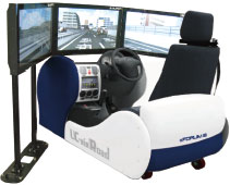
Compact Research Simulator
(2010)USD61,000
(3ch standard)Simulator for research
(including UC-win/Road DSop.)
Real car parts and Instrumentation
Steering for both side available, Automatic (Manual Op.)
Active Steering Wheel, MP (1-6 axis) option
(UC-win/Road is not included.)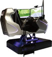
Driving Simulator
(2013)USD316,400
(3ch standard)3ch. 32” LCD monitor (including UC-win/Road DSop.)
6DOF Motion platform (payload 350kg)
5.1ch Speaker, Body Sound
Force feed-back steering system (SENSO-Wheel)
Accelerator/brake pedal system
Direction indicator, mission option
(UC-win/Road is not included.)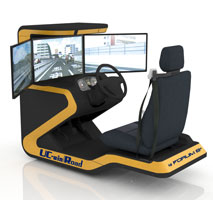
Compact Driving Simulator
(2014)USD36,000
(3ch standard)Steering wheel, accelerator/brake pedal system
(real car parts used)
Steering for both side available, Automatic (Manual Op.)
Active Steering standard
LCD instrument Op
(UC-win/Road is not included.)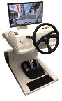
Simple Driving Simulator for seniors
(2014)USD14,500
(1ch standard)21.5” LCD monitor
Kinect™ sensor
Real car parts (indicator, wipers)
Realistic type steering wheel
Hazard lights
(UC-win/Road is not included.)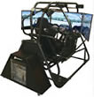
SimCraft Simulator
(2014)USD85,000
(3ch standard)3ch.40” LCD monitor
3DOF motion platform
High-grade steering controller for game
Accelerator / brake pedal (including Load Control Function)
*Motion configuration and other options are supported.
(UC-win/Road is not included.)Flight simulator (left), Racing simulator (right)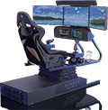
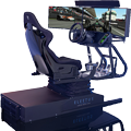
BlueTiger (2014)USD70,000
(3ch standard)3ch. 32” LCD monitor
2DOF motion platform
Operation interface for Flight Simulator
Seat vibrator
(UC-win/Road is not included.)
Motion Platform option,
*Custom tailored system integration development service,
installation service available at additional cost.
Drive type option supported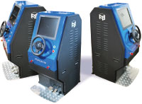
Demo Simulator (2007)USD10,000
(1ch standard)Simplified simulator
(UC-win/Road is not included.)
Compact type for exhibition/demonstration, Start/Stop button
Steering wheel, accelerator, brake installed
VR-Cloud® Cloud server setting / Rental price
VR-Cloud® Cloud server setting / Rental price
-
■Example of server construction (Per 1 data of UC-win/Road)
Product structureUC-win/Road UltimateUC-win/Road AdvancedUC-win/Road StandardVR-Cloud® Flash VersionUSD18,000USD12,000USD8,800VR-Cloud® StandardUSD18,000USD12,000USD8,800VR-Cloud® CollaborationUSD20,000USD14,000USD10,800■Specifications
ProductSpecificationsPriceSystemNoteUC-win/Road
and VR-Cloud®1. VR-Cloud® (per 1 server)UC-win/Road Ultimate,
UC-win/Road Advanced,
UC-win/Road StandardSee example
of server
construction2. Road data (Data processing)Data processing and optimization
are not required.Free3. Main component and data activationWhen using multiple sets of data,
resetting of schedule and task is required.Always activeServer rental4. Rental server fee
Basic fee:
UC-win/RoadVR data x1,
Simultaneous accessible client x5Available for:
1.FORUM8 server
2.Data center server
Network requirements
100MB - 1GB, Dedicated line,
best-effort network or
anything in betweenSee basic server
rental priceProductSpecificationsPriceSystemNoteVR-Cloud®
server and
internet settings1. IIS settings, server folder configurationWeb server operation
administrative cost
is not included.USD2,0002. VR-Cloud® Settings,
data reproduction,
operation confirmation3. VR-Cloud® webpage creationCreation of webpage and menu,
setting of linksPlease ask
our sales staff.* Setting cost is for 1 data per 1 server (CPU). Maximum concurrent usage 99(CAL=99 clients).
* System configuration is based on hardware specification and software we selected.
* Standard system settings and installation settings are included except operation administrative cost.■Basic Server Rental Price(Per 1 data of UC-win/Road)/ Rental fee rate:
Rental price rateBasic rental price2 weeks1 month2 month3 month6 month1 yearMore than 1 year per 1 monthBasic 5 clients *10.500.650.851.001.703.000.2Additional 5 clients *2Rental priceBasic rental price
3 month2 weeks1 month2 month3 month6 month1 yearMore than 1 year per 1 monthVR-Cloud® Flash Version / StandardBasic 5 clients USD3,000 *1USD1,500USD1,950USD2,550USD3,000USD5,100USD9,000from USD9,600Additional 5 clients USD600 *2USD300USD390USD510USD600USD1,020USD1,800from USD 1,920VR-Cloud® CollaborationBasic 5 clients USD3,000 *1USD1,650USD2,145USD2,805USD3,300USD5,610USD9,900from USD10,560Additional 5 clients USD600*2USD330USD429USD561USD660USD1,122USD1,980from USD2,112*1 Including server setting charge. The charge of data adjustment is not included.
*2 The charge is added per 5 clients.■ Reference : Supply Environment(Cloud server/line)
EnvironmentName (Reference)ServerDell PrecisionR5400 quad core Intel®Xeon® processor
E5450(2x6MBL2 cache 3.00GHz, 1333MHzFSB) x2
8GB(2GBx4) quad channel DDR2-SDRAM memory (667MHz, ECC)
1TBSATA3.0Gb/sNCQHDD(7200rpm) x2 SATARAIDLevel1(HDDx2) configuration
NVIDIA®Quadro®FX5800, 4GBDDR3memoryOSMicrosoft® Windows®7Professional64bit official version (Japanese/English version)
Windows Server(TM) 2003 SP1 Standard EditionProvider, domain nameStatic IP addressServer maintenance24-hour technical telephone support (with E-mail support) (24 hours a day, every day)
On-site maintenance service for five yearsInternet connectionUSEN BROAD GATE02 Optic business access Giga IP8, 1Gbps
Academic Price
An Academic License can be provided for educational purposes and used by teachers, lecturers, academic researchers, and students.
Academic Price
-
Product NameAcademy PriceUC-win/Road Ver.19 UltimateUSD15,360UC-win/Road Ver.19 Ultimate 5 licenses pack SubscriptionUSD23,870UC-win/Road Ver.19 Driving SimUSD10,240UC-win/Road Ver.19 Driving Sim 5 licenses pack SubscriptionUSD17,160UC-win/Road Ver.19 AdvancedUSD7,760UC-win/Road Ver.19 Advanced 5 licenses pack SubscriptionUSD13,310UC-win/Road Ver.19 StandardUSD5,040UC-win/Road Ver.19 Standard 5 licenses pack SubscriptionUSD9,020UC-win/Road Ver.19 CIM LiteUSD4,224UC-win/Road Ver.19 Multi User Client VersionUSD944UC-win/Road Ver.19 Presentation VersionUSD528UC-win/Road Ver.19 Cluster Client VersionUSD528
Version Update History
Version Update History
-
UC-win/Road Ver.19VersionReleased dateUpdated contents19.0.025/10/10
- UC Support AI and Design Support AI
- Road creation and editing on a 3D display
- Passthrough display support for VR devices
- Integration with the National Land and Traffic Data Platform (Road Traffic Census data)
Product Operation Environment
Product Operation Environment
-
Please check below.
> Product Operation Environment
Order / Contact Us
Order / Contact Us
-
■Inquiries about UC-win/Road
Contact us from Sales inquiry or email to ist@forum8.co.jp or forum8@forum8.co.jp■Sales Office
>> Sales offices
-Bridge/Tunnel-
3DVR is effective to select the type of bridge. Design data such as Engineer's Studio® can be applied to bridge models with a"3ds" extension. Examination of bridge type and color, and adjustment of construction shade according to seasons and time are available. Driving, walking and flight simulation are effective to landscape examination.
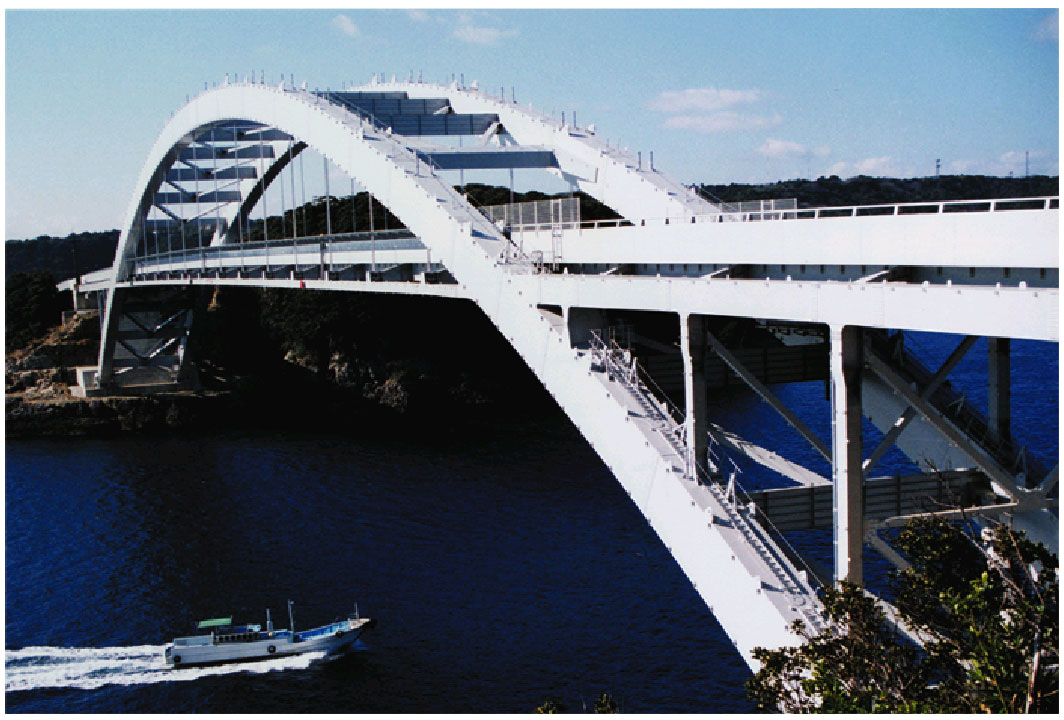

▲Comparison of VR Model with actual photograph (Left: actual photo captures; Right: UC-win/Road screen)
Data provided by Nippon Koei Co., Ltd. (Kushimoto Bridge/ Myouga Loop Bridge)
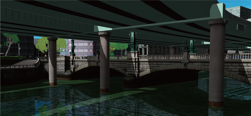
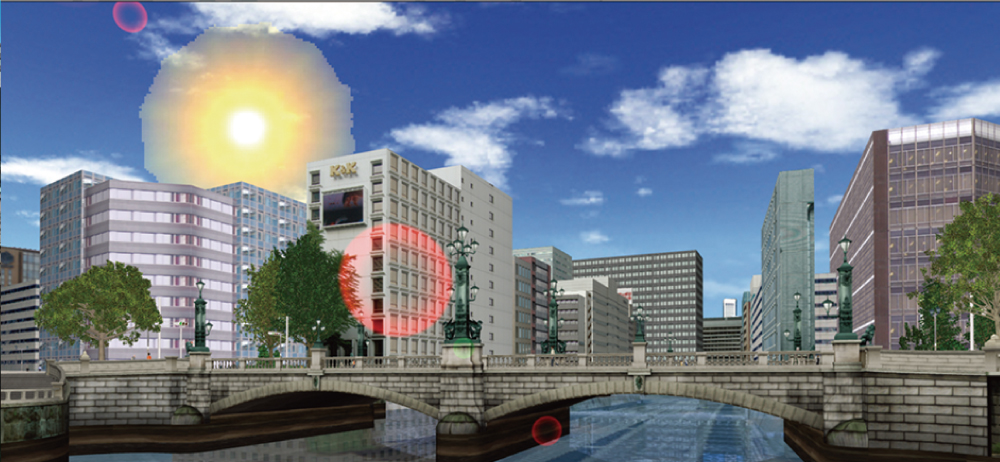
▲Visual comparison of a bridge before and after the removal of elevated highway on Metropolitan Expressway (Nihonbashi River)
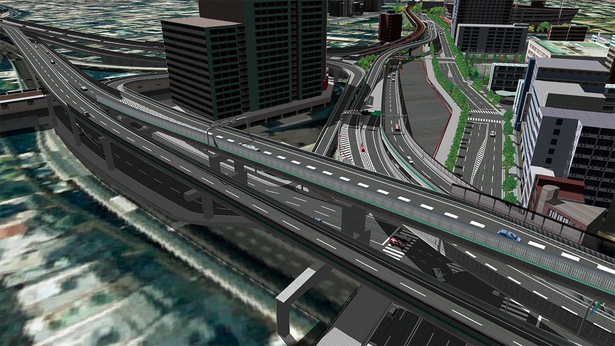
▲Shadow is depicted in detail with the high precision rendering
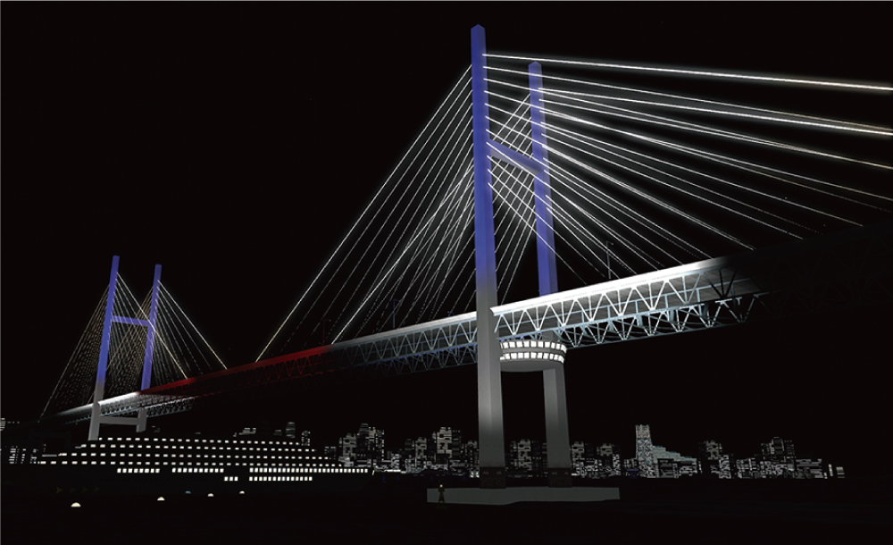
▲Lighting up bridges can be displayed.
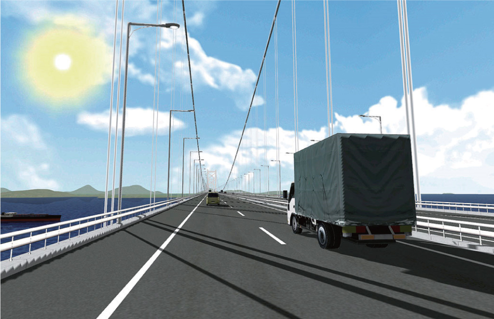
▲Scene of a truck running over Great Seto Bridge
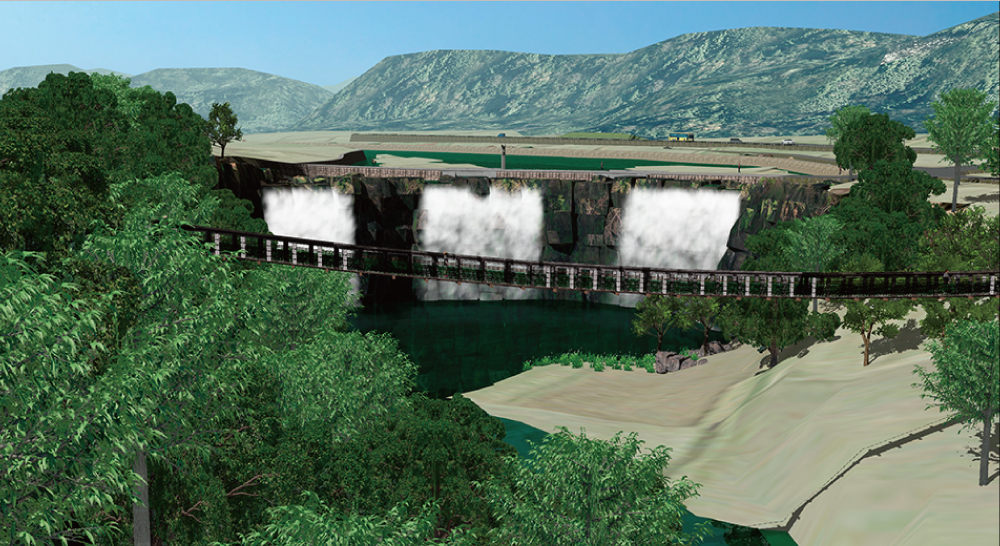
▲Suspension bridge

▲Engineer's Studio® 3DS export

▲Inside the tunnel
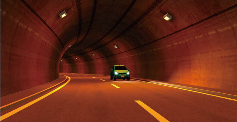
▲Tunnel entrance design
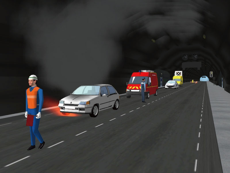
▲Training system for tunnel administrator
via VR (BMIA, France)
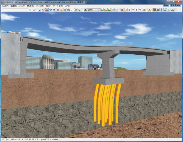
▲Export 3D models from Engineer's Studio®

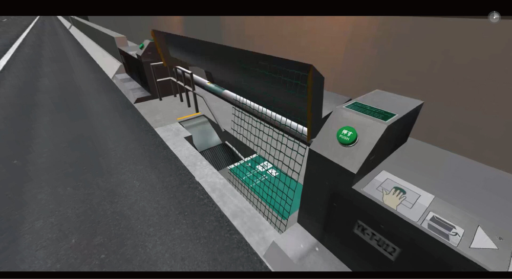
▲The 17th 3D・VR Simulation Contest on Cloud
Essence Award "VR simulation of evacuation from Metropolitan Expressway Yokohama Kita line"
Kanagawa Construction Bureau, Metropolitan Expressway Company Limited
-Traffic-
Traffic flow and vehicle profiles can be altered in traffic simulation, which also takes into consideration vertical slopes and the vehicle performance. The traffic after the opening of a new bypass or a large attraction, such as a shopping mall, can be simulated, and linkage with traffic analysis software enables UC-win/Road as a simple visual 3D traffic simulation.
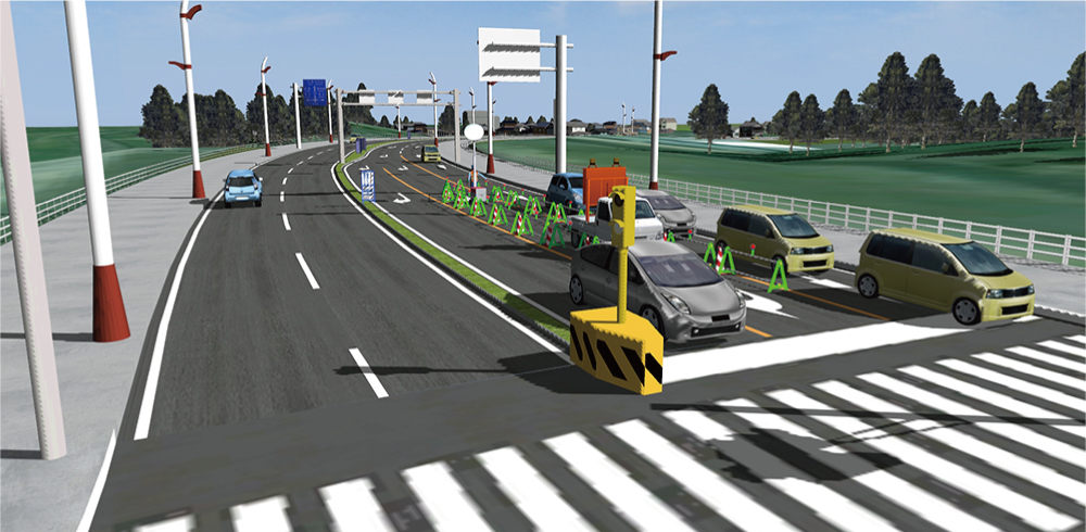
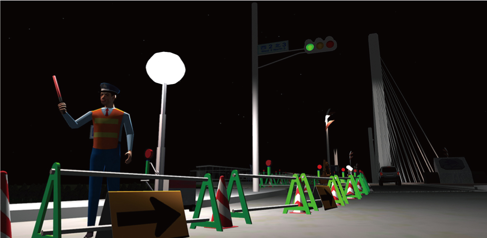
▲12th 3DVR Simulation Contest Grand Prix
"VR Simulation for Traffic Regulation to Divert Traffic During Night Construction" Iwasaki CO., LTD.
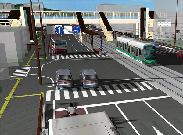
▲10th 3DVR Simulation Contest
Honorable Judge Award "VR simulation for consensus creation in the traffic nodes improvement project"
Asahi Sokuryo Sekkei Co., Ltd
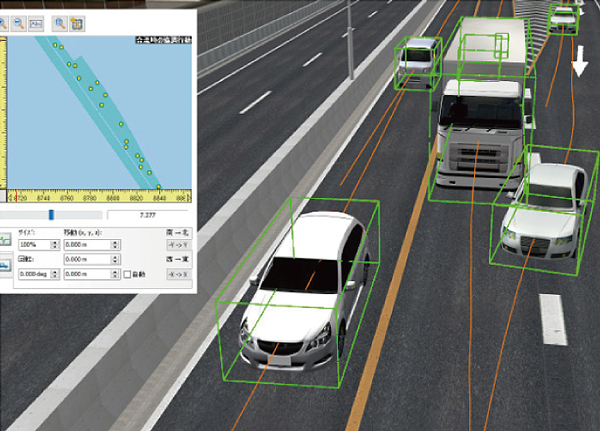
▲18th 3DVR Simulation Contest
Honorable Judge Award "Vehicle trajectory simulation on Hanshin Expressway"
Hanshin Expressway Company Limited
●Micro Simulation Player Plugin
Micro Simulation Player is the function to run various types of simulation animation which is depicted as 3D model movement. It is capable to record and play a traffic flow as a result of UC-win/Road and other traffic simulation.
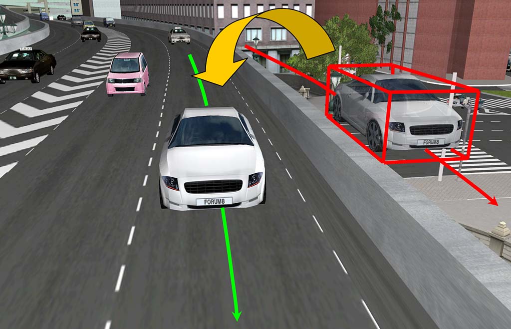

●OSCADY PRO Plugin Traffic light designing software
Oscady Pro allows automatic setting of signal phase and arrangement, and optimized signal capacity and congestion, and gradal and swift optimization of traffic signal.
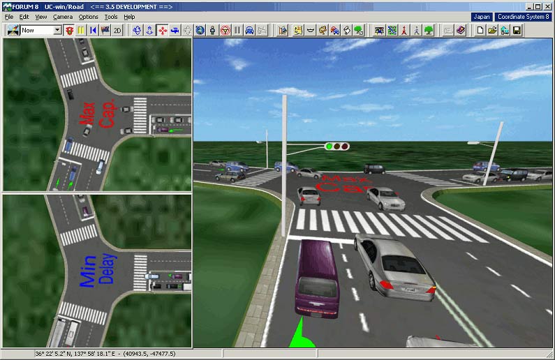
It's possible to read the result of traffic flow analysis of VISSIM and to simulate it.
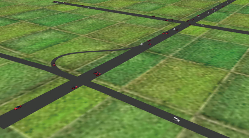

Vehicle behavior and signal phase from Aimsun can be reproduced real-time within the UC-win/Road 3D environment.

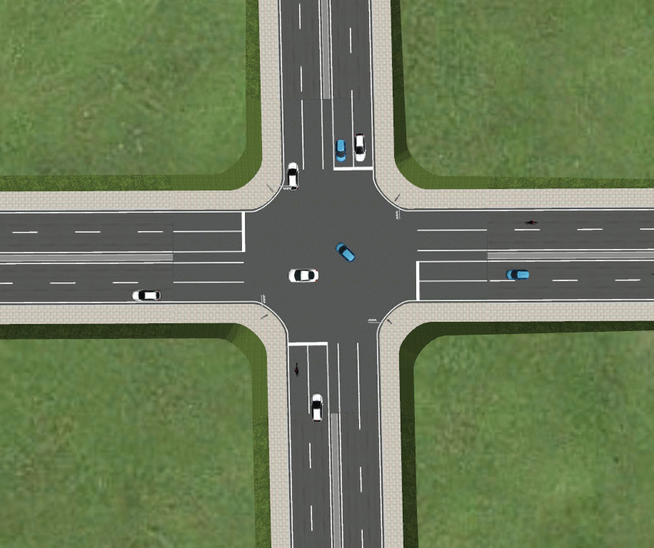
●Traffic simulation Clearing house
Inspection points of UC-win/Road is posted.
https://www.forum8.co.jp/topic/up68-p4.htm
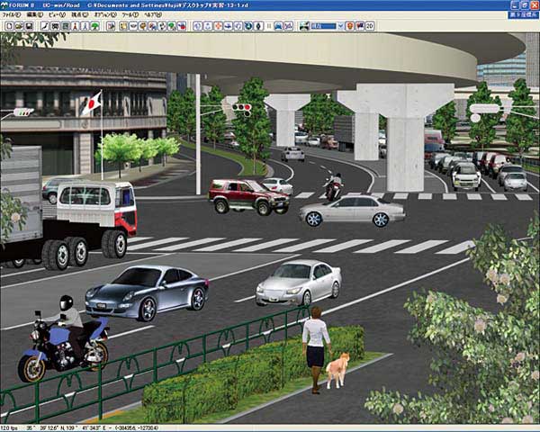
-River-
For use in river improvement and maintenance projects, movement of the water and reflection on the surface can be utilized.
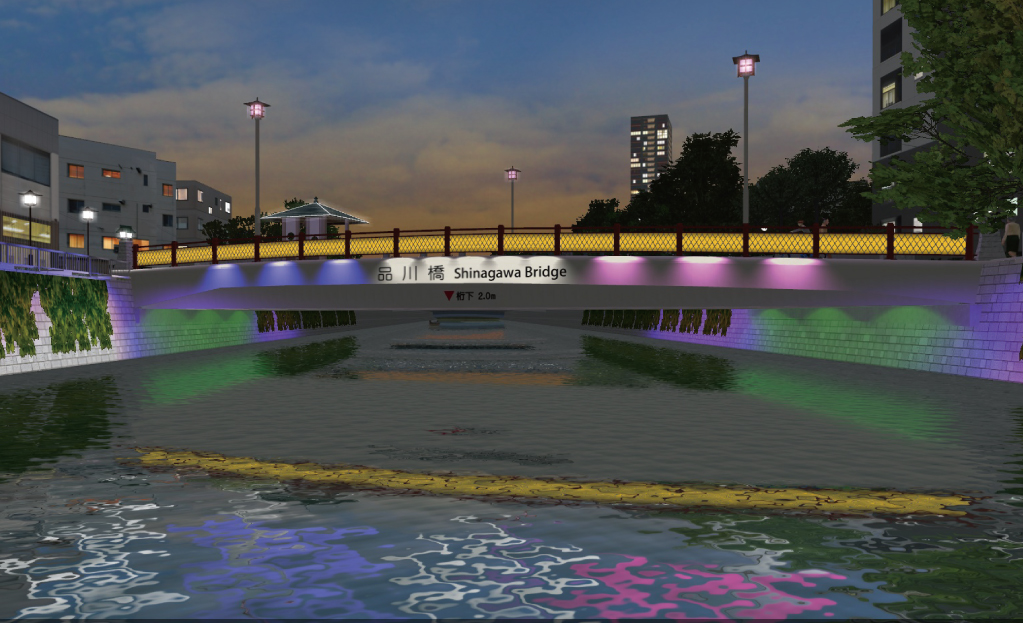
▲第18th 3DVR Simulation Contest
Honorable Judge Award "Bridge light-up simulation along Meguro River"
By KEIKAN SEKKEI TOKYO Co., Ltd.
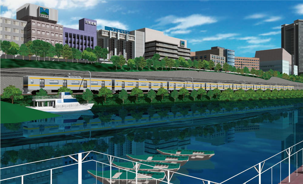
▲6th 3DVR Simulation Contest Excellence Award
"Hosei University around Ichigaya Campus VR Simulation" By Civil and Environmental Engineering , Faculty of Engineering and Design, Hosei University
-Railroad-
New transportation system such as railway, can be available as well as road simulation. It is easy to make plans of crossing with an overpass or underpass with 3DVR and redevelopment projects in station square and pedestrian deck plans are available.
A variety of system constructions including railway simulators for R&D, education and training, and publicity work are also provided.

▲Railway simulation
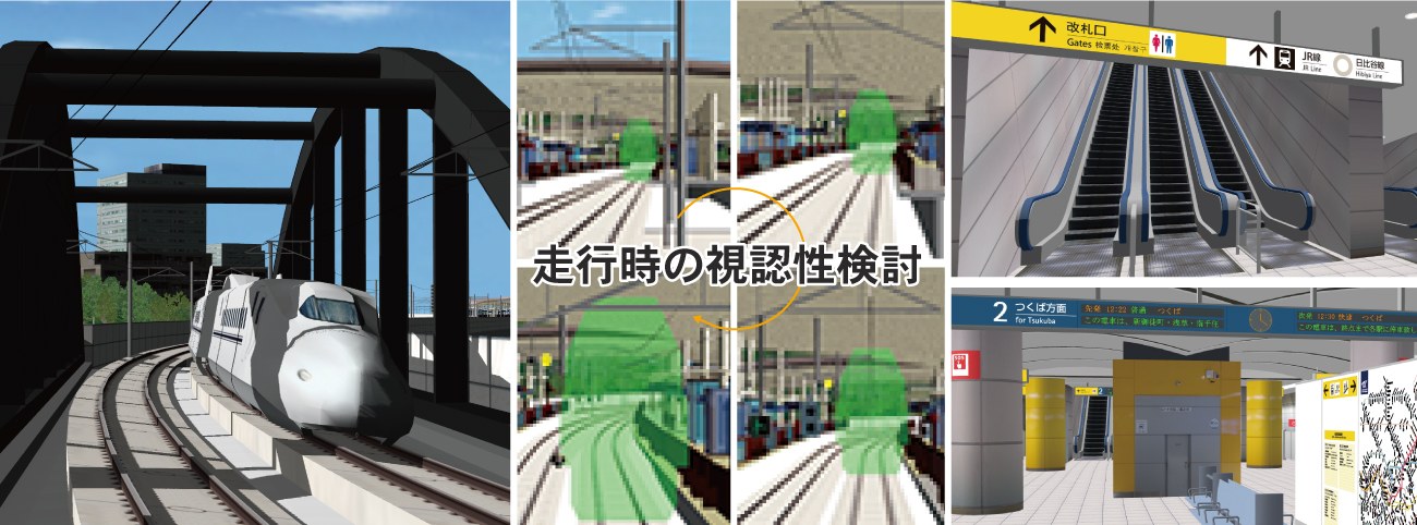
▲10th 3D-VR Simulation Contest
Grand Prix "System for checking the position where equipments are installed" By Japan Railway Construction, Transport and Technology Agency
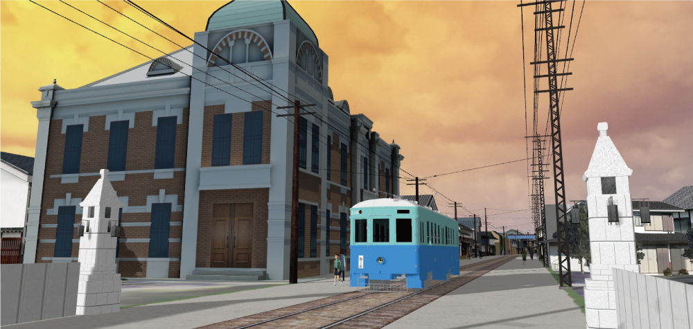
▲16th 3D VR Simulation Contest
2nd Prize "Reproduction of the tramway line and its surroundings in Omuta city" By Keisuke Ijiri
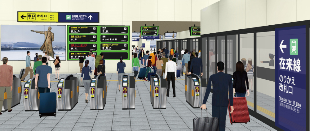
▲17th 3D VR Simulation Contest
Grand Prix "VR simulation for Hokkaido Shinkansen Sapporo station design and construction" By Hokkaido Railway Company
-Harbor/Airport-
For models of harbors and airports, simulation of a vast area is available with aerial pictures. Sea routes of vessels can be defined through path configuration, allowing visual expression of diverse vessels sailing. Also, by defining airplanes as flight models, take-offs and landings can be visualized. With the seacoast and undersea models, there are reflection expressions and diverse 3D models available.

▲16th 3D VR Simulation Contest
Grand Prix "Education training of Haneda Airport by VR simulator" By Meiwa Sky Support Co., Ltd.
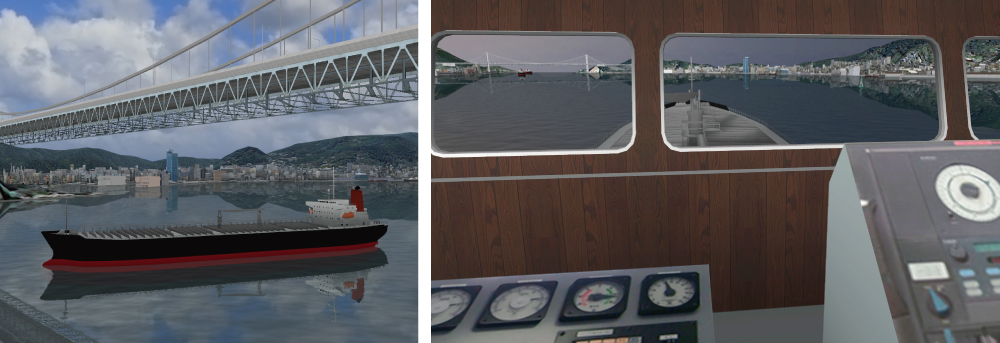
▲17th 3D VR Simulation Contest
2nd Prize "VR data for ship operation simulator"
By AKISHIMA LABORATORIES (MITSUI ZOSEN) INC.
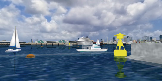
▲Sample model of Kobe port
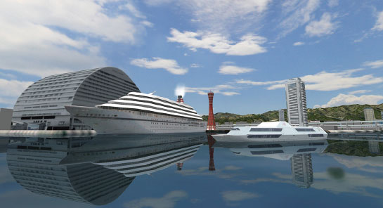
▲Sample model of Kobe port
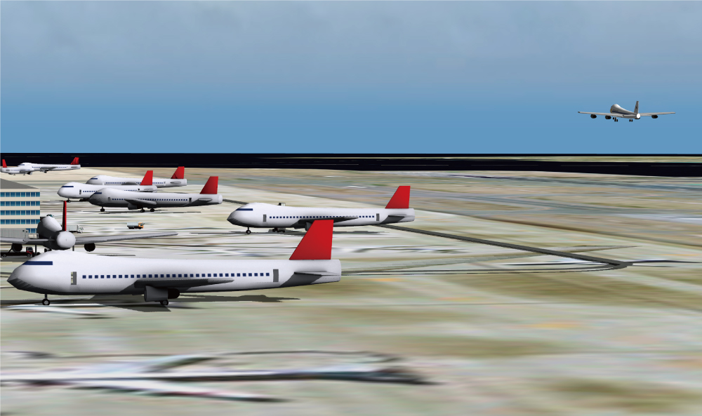
▲Take-off and landing of airplanes can be defined by flight paths
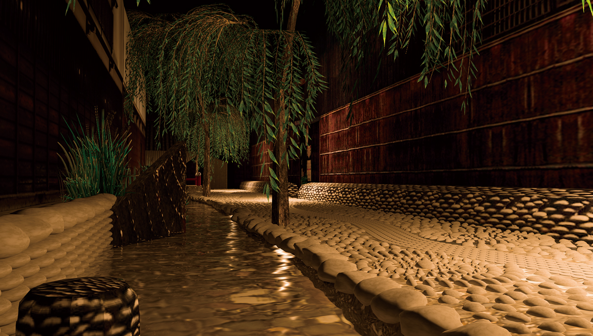
▲Examples of modelized riverside districts and water channels (Gujo Hachiman)
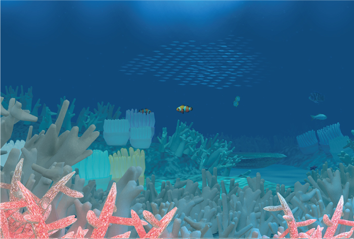
▲Undersea image models
Coral reefs = 3D trees. Fish = MD3 characters
-Park/Town-
The image can be visualized by walking through the whole image or switching through plans so that scenery plan consideration is possible. A wide range of tree textures and 3-D trees are useful for planting evaluation in designing parks and housing development areas, or effects on traffic and human flow caused by the plan.
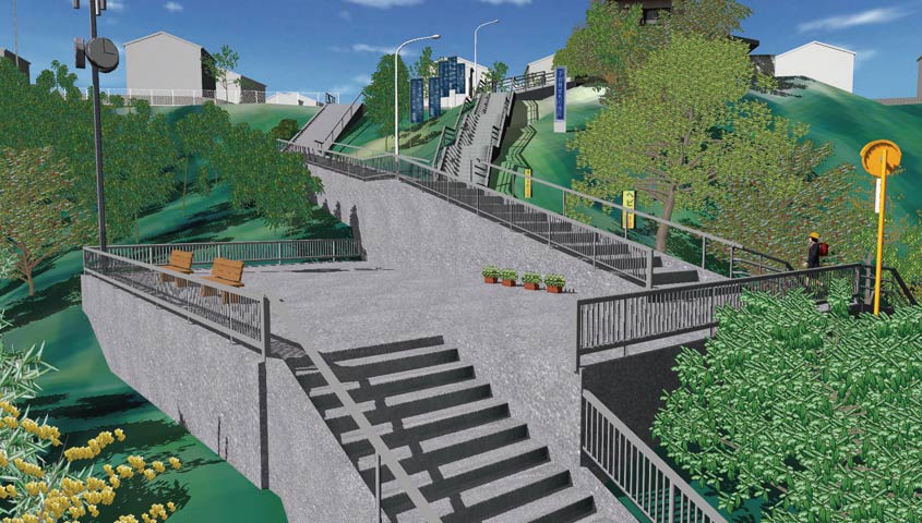
▲10th 3DVR Simulation Contest
Honorable Judge Award Regional Construction Award
"Simulation for improving the route taken by students going to and from school"
By Tatsumi Architects & Engineers
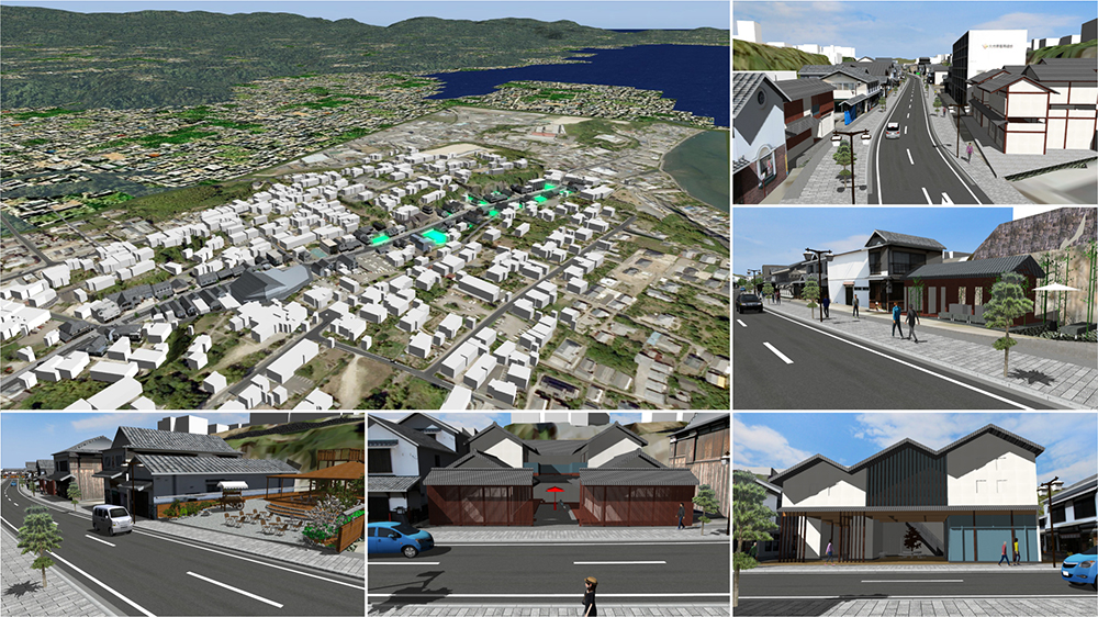
▲14th 3DVR Simulation Contest Grand Prix
Kitsuki City jokamachi (castle town) future proposals
by Kitsuki City, Oita Prefecture
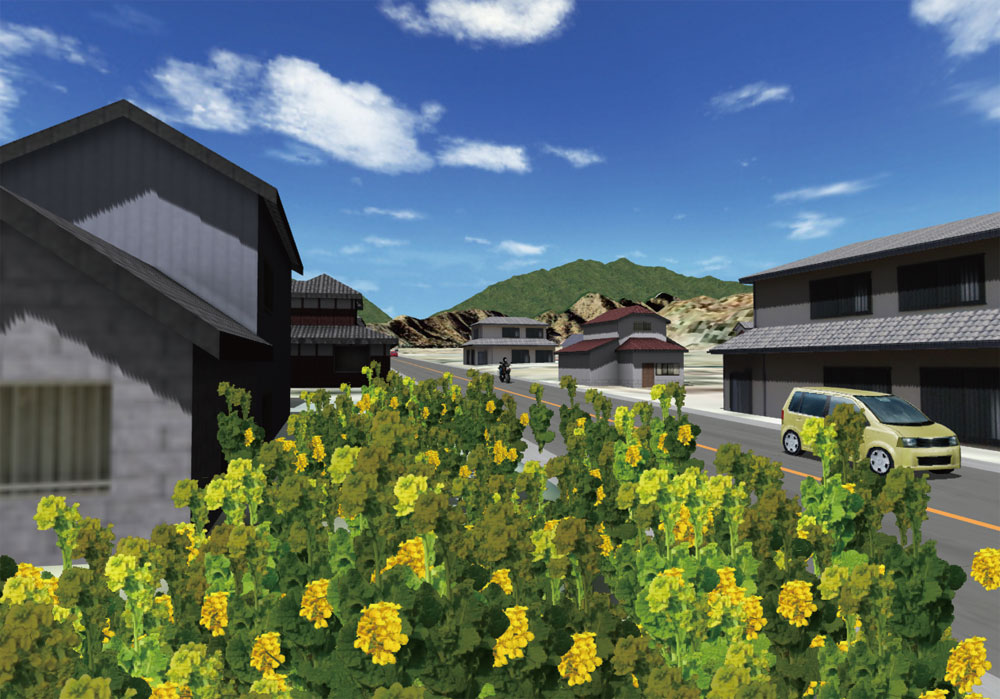
▲City and Architecture blog / Shinano Omachi
(NPO Workshop for Sustainable Community)
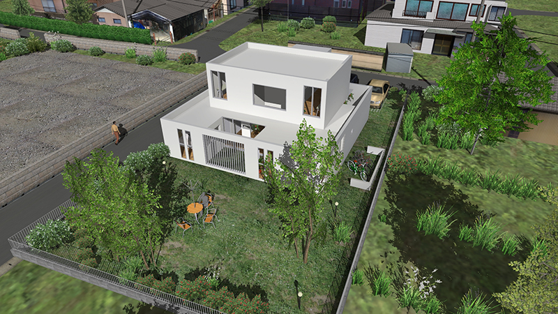
▲13th 3DVR Simulation Contest
Design Award "Residential Building Design VR Simulation for N House" By atelier DoN
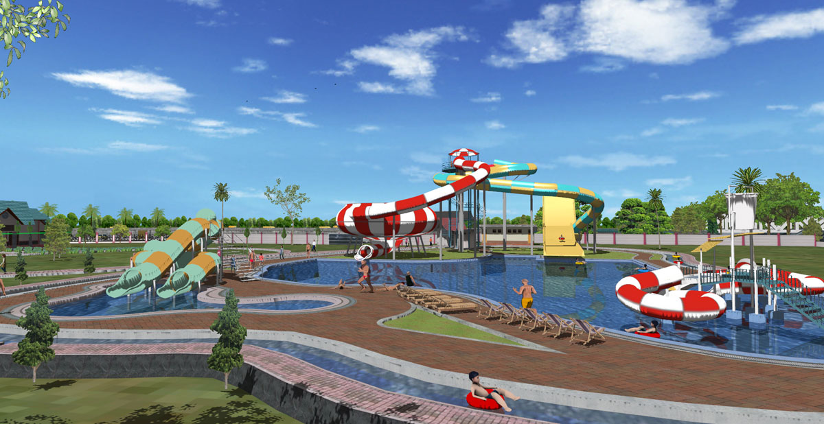
▲9th 3DVR Simulation Contest
Nomination Award "BANJAR Water Park"
by FUJICON PRIANGAN PERDANA, PT (Indonesia)
-Urban planning-
For designing cities and streets, tree planting evaluation and tree type selection are available, offering simulations in the four seasons in 5 or 10 years from now. For improvement of streets and redevelopment of train station neighborhoods, 3D traffic streams and dynamic urban area representations with 3D human models are useful. With the artificial light feature, which switches through daytime and nighttime, the landscape can be evaluated at day and night.
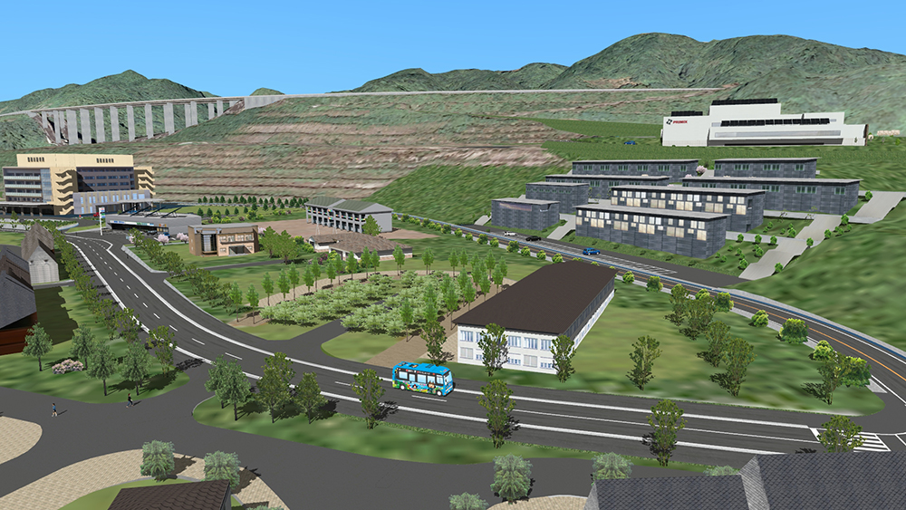
▲14th 3DVR Simulation Contest
Regional Construction Award "Dream Zone - Creating the Town You Want to Return! - Awaji City Yumebutai Sustainable Park, Compact City Project" By Awaji City Hall, Hyogo Prefecture
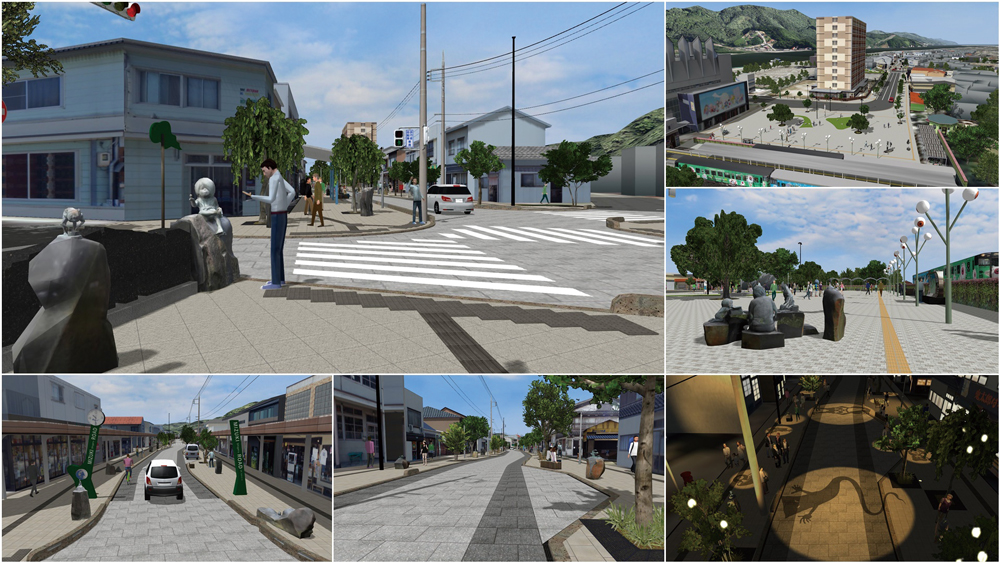
▲15th 3DVR Simulation Contest
Grand Prix
"Mizuki Shigeru Road in Sakaiminato City" By Sakaiminato City
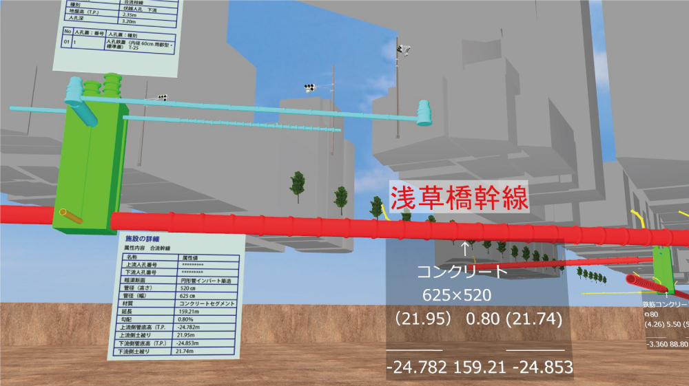
▲16th 3DVR Simulation Contest
Idea Award
"Integration of 3D models from sewerage pipe line investigation data" By Kanro Jyoho Katsuyo Yugen Sekinin Jigyo Kumiai (Limited Association of Pipeline Data Utilization)
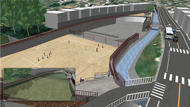
▲17th 3DVR Simulation Contest
Honorable Judge Award "VR data utilized for Nanase River renovation plan" By Kyoto Kogakuin High School

▲Landscape assessment of day and night (Daytime)
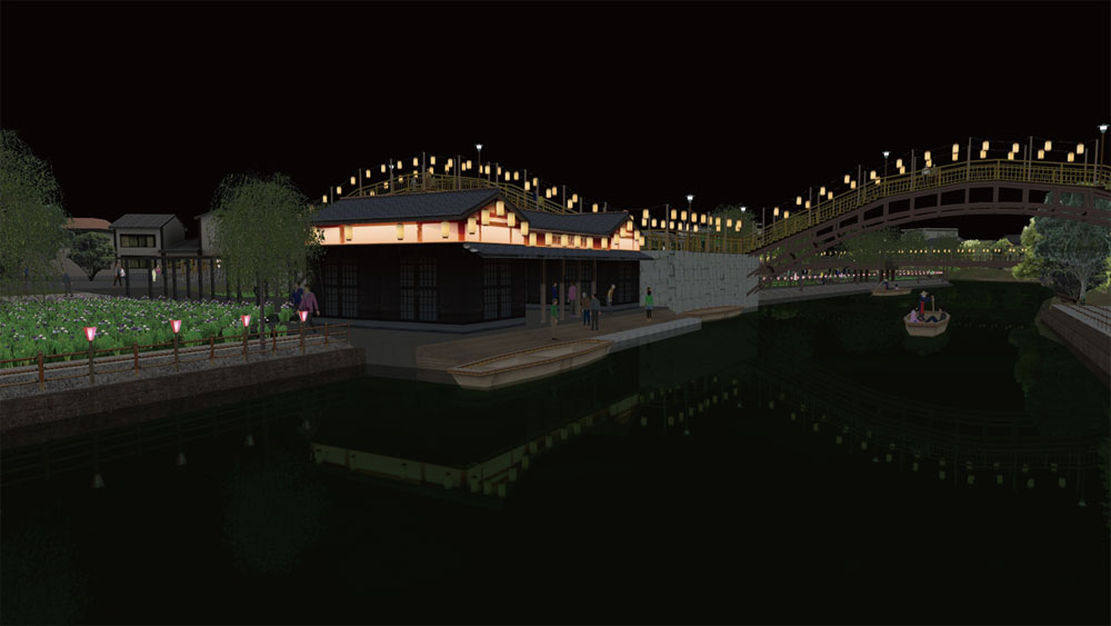
▲Landscape assessment of day and night (Nighttime)
"City and Architecture Blog" (Japanese) by Assoc. Prof. Tomohiro Fukuda is open on Up&Coming. FORUM8 staff tries to model 3D digital cities introduced by Assoc. Prof. Fukuda.

▲ Sule Pagoda and roundabout
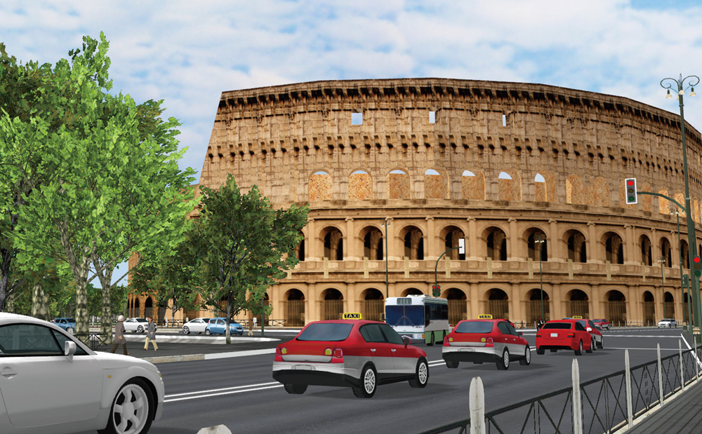
▲ Colosseo

▲ Tsurugaoka Hachimangu
-Road Simulation-
For evaluation of slope works such as cutting and banking of the terrain, and small ramps, simulations of internal/external landscapes depending on the traveling speed are available. With plentiful road options, horizontal crossings as well as overhead crossings, tunnels, and bridges can be generated easily, offering visual definition of complicated crossing shapes, textures, running routes, and traffic control. The On/Off ramp definition feature allows quick creation of intricate interchanges. Profiles can be set by hourly traffic volume and by car type for traffic jam simulations and traffic volume comparison simulations in planning bypass routes.
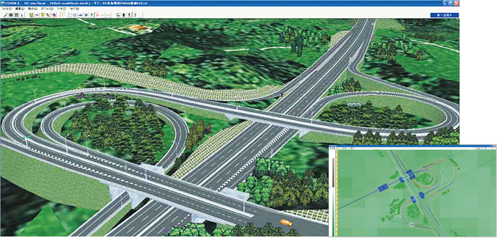
▲ Interchange

▲ Rotary
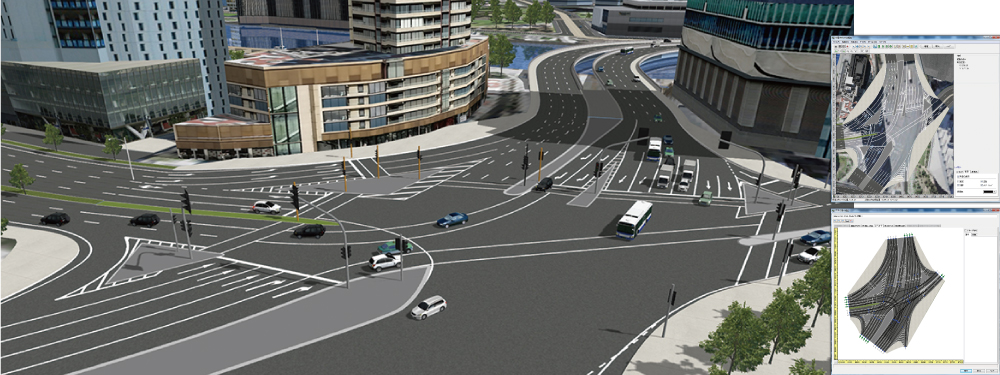
▲ Intersection

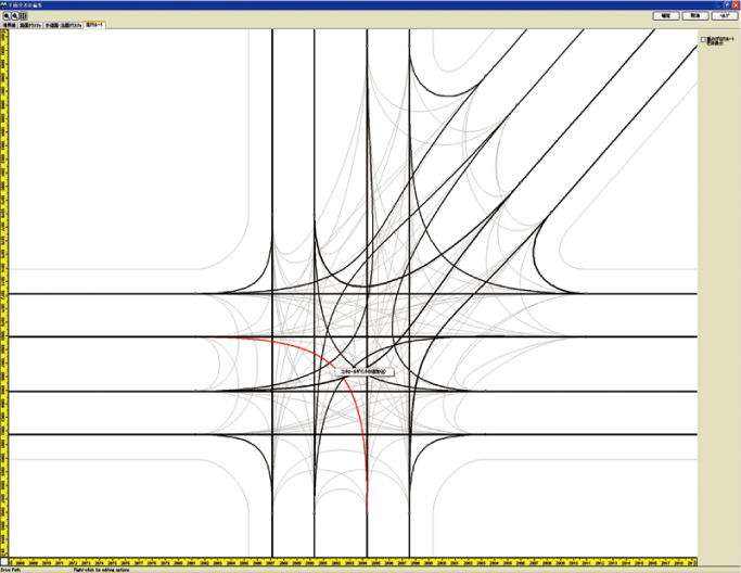
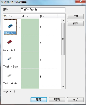
▲Traffic Generators/Flow
Traffic generation through rate setting by car type and hourly traffic volume setting
and traffic stream simulation that allows car collision control.
From upper left, traffic route, hourly traffic volume by route, and configuration screen for car rate by type.
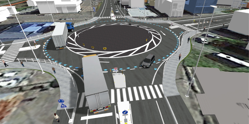
▲18th 3D VR Simulation Contest
Nomination Award "VR simulation of social infrastructure planning" By Toho Development Co., Ltd.
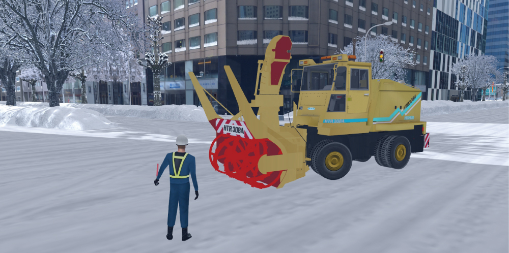
▲18th 3D VR Simulation Contest
Idea Award "Snow blower simulator" By NICHIJO CORPORATION
1.動作環境
- 特別なパソコンが必要でしょうか。
-
最近では市販のPCで、オンボードのグラフィック機能により動作可能となっていますが、グラフィック機能がより強化された機種であればストレスなく3DVRを扱うことができます。
推奨スペック例:
OS Windows 7、8.1 の64bit版
CPU Intel Corei5、Corei7
メインメモリ 8GB以上
グラフィック Open GL2.1以上をサポートしたグラフィック
推奨)
デスクトップ:
NVIDIA Geforce GTX 970、980
NVIDIA QUADRO K5000、K5200、K6000
ノート:
NVIDIA Geforce GTX 980M
ディスプレイ 推奨解像度 1920×1080以上
ご不明な点についてはお問い合わせください。営業窓口(フリーダイヤル):0120-1888-58
営業問い合わせフォーム : https://www2.forum8.co.jp/cgi-bin2/eigyo.htm
- Radeonのビデオボード搭載のパソコンで問題ないか。
-
OPENGLに対応ということであれば、基本的には問題はないと思われます。但し、NVIDIAのボードで問題なく描画が行えるデータが、描画できない場合が生じる可能性があります。
また、問題が発生した場合、即時解決対応ができない場合があります。できましたら推奨のNVIDIAのボードをご利用いただきますようお願いいたします。 - (株)HORI製のステアリングコントローラEXは使用可能か。
-
システムでサポートしているステアリングコントローラは通常PCへ接続可能なコントローラを採用しています。
(株)HORI製のステアリングコントローラEXはマイクロソフト社のXbox用ですが、このデバイスをPCへ接続し通常のゲーム等にて使用可能ですので、システムにおきましても使用可能です。しかしながら、弊社で実際に確認したわけではございません。その点は予めご了承ください。 - PCにおいて「.NET Framework 3.0」が利用されている場合、何か問題は発生するか。
-
弊社で確認したところでは「.NET Framework 3.0」がインストールされているPC上でも何ら問題なくシステムは動作しています。
- UC-win/RoadをデスクトップのPCで使用するに当たって、推奨されるスペックなどを教えてください。
1) OS
2) CPU(クロック数も)
3) メモリ容量
4) ビデオメモリ容量
5) 画面解像度
6) ハードディスク容量
7) 画面の物理的な大きさ(15インチ、17インチ等)
8) プリンタポート等、特別に必要なハードウェア
9) その他注意事項があれば教えて下さい。 -
UC-win/Roadを使用する際に必要な環境のスペックは、下記ページをご参照ください。
>> UC-win/Road 製品利用環境
また、7)~9)については、以下の通りです。
7)画面の物理的な大きさ→ 大きいほど見やすいといえます。
8)プリンタポート等、特別に必要なハードウェア
→ 運転などを行う場合、上記コントローラが必要です。
9)その他注意事項があれば教えて下さい。
→ メモリやビデオカードは動作に影響が大きいので、その点にご注意頂きご検討ください。
2.データ作成
- Additional fee読込みは、別データからのモデルを取り込むことと考えて良いか?
-
その通りです。更に同じ景観の道路を取り込むと、道路も別モデルとして読み込みますので注意が必要です。
- 景観保存位置を削除できないが?
-
景観保存位置の編集画面で「削除」ボタンが有効にならないのは、スクリプトで設定されているためと考えられます。
- モデルのグループ配置の電線設定を利用して、ガードケーブルを設置したいと思っています。
そこで、電線部分をケーブルにみせたいので、黒色から、シルバー系の色にする方法を教えて下さい。 -
電線のケーブル色を変更するには、ケーブル配置した後、電線部分をマウスでクリック選択し、表示された「電線の編集」画面から色の部分をクリックし、任意の 色を設定してください。なお、現時点ではデフォルト色の設定や一括で変更する機能がございません。そのため、面倒とは存じますが、柱間ごとに画面を表示し 個別に変更して頂きますようお願いいたします。
- 景観位置を座標と高さを指定して設定できないか。
-
メイン画面のアンダーバーに、現在位置の座標が表示されます。この座標は世界測地系です。それを参照しながら、景観位置を保存すれば可能です。ただし高さの指定は出来ません。
座標入力および、高さ設定については、飛行ルートを利用すれば可能です。平面図で飛行ルートを定義し、起点位置を座標入力して下さい。飛行ルートの縦断で 起点高さを設定します。飛行ルートの起点に動作制御点を設定し、速度0とします。飛行し、その位置を保存して下さい。 - 照明が点滅する表現をしたいが、できるか。できるならばどのような方法か。
-
モデルの可動設定でできます。UC-win/Road起動時に登録されているモデルのうちBrinkerというものがありますので、それを参照して下さい。
点灯しているテクスチャをマッピングしたオブジェクトと消灯しているテクスチャをマッピングしたオブジェクトをあらかじめモデルに用意しておき、UC- win/Roadに読み込んだあとモデル編集の可動設定で、それらを交互に見える位置に入換えることで点滅しているような表現となります。 - ルート飛行の際、進行方向を見てしまうが、視線方向を指定できるか。
-
Look at Me という機能を使い、見たい方向を設定できます。手順は以下の通りです。
- 見たい方向にあるモデルの編集画面「制御対象」にチェックを入れます。
- 道路平面図で飛行ルートに動作制御点をAdditional fee、対象[モデル]を設定して下さい。
- コマンドに「LOOK AT ME」を設定して下さい。
以上で飛行すると、設定したモデルに視線を向けた状態で飛行します。
- RoadからCivil3Dへ地形データをエクスポートする際に、どの程度の規模までエクスポートできるのか。
またその逆にCivil3DからRoadへ地形データをインポートする際にどれ程度の規模までインポートできるのか。 -
RoadからCivil3Dへ地形をエクスポートするときは、基本的にはRoadデータ範囲全体までエクスポートさせることが出来ます。
Civil3DからRoadへインポートする場合は、最大20km x 20kmの範囲でインポート可能ですが、マージの際は現在のRoadの範囲に制限されます。 - 交差点を車両に移動して走行時、がたがたと揺れる。揺れない方法はないか。
-
走行ボタンで走行するのではなく、車両に移動して走行した場合、交差点では、路面の変化に応じた挙動となります。交差する道路の縦断勾配や横断から互いにすりつけを行いますが、すりつけた路面状態を走行時に反映しています。
- 車道がシフトするにつれて、ゼブラの位置が変化するような場合、どのような設定をすればよいか。
-
ゼブラ帯の変化は、Transitionを使い設定します。添付頂いた計画の場合、以下の点に注意してTransitionを設定して下さい。
- 同じ方向の車線間のゼブラのテクスチャは、「断面の詳細」のギャップに設定
- 中央分離帯のゼブラのテクスチャは、車道と車道との間の断面に設定
- Transitionの前後でノード数(頂点の数)を一致させる必要があるため、ゼブラがなくなる位置の断面にも幅0のゼブラのテクスチャの断面を設定
- Transitionの「起点側の曲率」「終点側の曲率」を適切に設定
- 飛行ルート飛行中に正面ではなく角度を付けて見たい。
-
「道路平面」の画面で、飛行ルート上でマウスを右クリックし、「Additional fee-動作制御点」を選択します。
次に「編集-動作制御点」で、コマンドに「Sloly Turnheadもしくは、Turnhead」を選択し、角度を入力します。 - 3車線から2車線への車線変更部における車両の優先性について
3車線から2車線に車線が絞られる箇所において、第1車線をなくし、第2・3車線による2車線道路にしようとした場合、第1車線を走行してきた車両が第2車線よりも優先され、第2車線の流れが低下してしまう現象が出ている。これをうまく処理する方法は無いか。 -
3車線から2車線になるところで、確かに外側から1車線目の走行車が2車線目の走行車より優先されるように見えることを確認しました。
基本的には1車線目の走行車が2車線目に移れると判断したときに1車線目の車輌が2車線目に車線変更し、移れないと判断したときは1車線内に停止します。 1車線目の車輌が2車線目に移動しているときに2車線目の車輌が遭遇したときは、2車線目の車輌が衝突回避から、そのまま停止し、この停止が後々まで続い て渋滞することになります。 - 路線別生成交通量の車線への割り振りに付いて
仮に、片側2車線の道路で、生成交通量が500台の場合、恐らく各車線250台ずつに割り振って流していると思うが、これを7:3に割り振って流したい場合は、どのように設定すればよいか。 -
以下2つの方法があります。
- 各車線の起点側にオンランプを接続し、その各々に対して7:3の割合で走行車を生成するようにする。但し、車線毎にランプを接続させるためにはオンランプの位置をずらす必要があります。
- 考慮する区間手前に車線変更の動作制御点をAdditional feeし、或る車線の走行車を隣の車線へ7:3になるように設定する。
これらの方法のうち 2 については、車線変更時に渋滞が発生するかもしれません。そのため今回の場合は 1 による方法をお勧めします。
- 交通量の生成方法について
以前、この件について質問したところ、ポアソン分布に基づいて生成させているという回答を頂いた。仮に、フェーズ上3600秒、500/hrとなっていた場合、具体的にどのように交通が生成されるのか。 -
交 通流の生成にはポアソン分布を使用しています。ポアソン分布は、t 時間当たりに x 件の事象の発生確率を示します。確率ですので、平均的には同じであっても、或る時間と別の或る時間とでは必ずしも生成台数が一定ではございません。そのために或る時は少なく、別の或る時は沢山の車輌が生成され、それが画面に表示されます。
基本的に車輌の出現に関するフェーズの設定は、有効にした行に関して入力した時間の間、時間台数の交通量を生成するという意味になります。1行のみの場合 は入力した時間にかかわらず、設定した交通量(台/hr)で生成します。この設定には複数行の入力が可能です。
それは、設定した位置より手前側に信号を伴う交差点があると考えると分かり易いと考えます。基本的にその交差点の信号フェーズがここの入力の時間と考えれ ば良いです。例えば、或る信号の青のフェーズが30秒で赤のフェーズが10秒の場合、また交通量が500台/hrの場合、1行目時間->30、交通 量->500、2行目時間->10、交通量->0の様に入力します。信号のあるフェーズが3600秒には基本的にはなり得ませんので、 入力項目内容をご理解の上ご使用ください。 - バスを一時停止後発進させたい。
-
以下の順に設定して下さい。
- バスモデルをポーズのみの可動設定を行う。
- バスを飛行体(走行車)にAdditional fee。
- 動作制御点を設定。
1行目 速度0km
2行目 コマンド指定と再開速度の指定
- 道路の建築限界4.5mを確認するために、たとえば路面から対象物の高さを計測する機能などはあるか。
-
計測機能は、モデル中心間の水平距離のみです。高さ等を確認するには、工夫が必要です。
建築限界を確認するための方法として考えられる例を以下に示します。- 目盛りの入った定規モデルを作成し、それを移動させながら確認する。
- 建築限界の範囲を示すモデルを作成し、それを当ててみるか、走行させる。
- 建築限界の範囲を示す断面を作成し、表示非表示チェック、透過などを使い必要に応じて確認する。
以上のいずれかの方法を試して下さい。
- 道路断面で作成した平場に樹木を効率よく配置するにはどうすればよいか。
-
「道路付属物」として配置いただくのがもっとも適しています。但し、画一的になりますので、個別に配置するなど工夫が必要です。
- 駅前ロータリーの道路はどうすれば作れるか。
-
まず、ほぼ1周する道路を定義します。縦断線形で一方向の断面を設定し、道路編集の平面画面に戻ります。
道路の両端部に黄色三角が表示されていますので、オフランプとオンランプを接続します。
これで周回道路が作成できます。 - 現在、設計前、設計後の切り替えスイッチを使い複数の案を切り替え表示させている。
案が4つ以上あるため、パターンを増やしたい。 -
「オプション」-「景観のモデル表示」-「景観のAdditional fee」で現在、設計前、設計後含め、最大20パターンまで増やすことが可能です。
増やした分の景観の名称は「名称の変更」で変更することが出来表示切替はチェックの入り切り、また、その状態で配置したものは初期値としてその景観のみチェックが入った状態となります。
表示切替は、プルダウンによる切り替えのほか Ctrl + Shift + 数字(2桁も可能)を押し、Ctrl + Shiftを放すと、その数字の景観に切り替わります。 - FORUM8名古屋事務所のサンプルデータで花火の処理をどのようにしているか教えてください。
>> FORUM8名古屋事務所 サンプルデータ (UC-win/Road Web Viewer) -
花火が打ちあがる過程の画像を数枚の板状のオブジェクトにマッピングした3DSモデルを使っています。可動設定により、順次表示させることで、花火を表現しています。
RoadDBにいくつか登録されておりますので、ご確認ください。
「3Dモデルの読み込み」-「ダウンロード」-花火で絞込みを行ってください。 - UC-win/Roadでビデオを再生できるか。もしくはビデオに近いイメージ(10-30フレーム)で再生できるか。
-
ビデオの再生は、スクリプトの中で可能です。(Q2-19.のとおり、ご覧になられた花火はビデオではなく可動モデルです。)
スクリプトの「マルチメディア」-「ビデオ再生」で 《 製品のインストールフォルダ 》 Video に登録されているAVIファイル指定すると、スクリプト実行中に、設定したタイミングで再生させることが出来ます。 - Civil3Dで作成したデータをUC-win/Roadに読み込みたい。どのようにすれば良いか。
-
LandXMLによるデータのインポート、エクスポートは地形、平面線形、縦断線形、横断の4つについて可能です。
Civil3Dで「LandXMLに書き出し」そのデータをUC-win/Roadの「ツール」-「LandXMLをインポート」から読み込んでください。 - 3車線道路の中央より1車線をバス専用にしたい。特に道路の起点からそのように振り分けたい。
-
道路の起点からバス専用車線を作るには、次の手順で行います。
- 現在の起点の断面左3車線-右3車線を5mの位置に新たに設定します。
- 起点の道路断面を新しく左1車線-右3車線として作成します。
- 5mの位置でオンランプ接続が可能となるため、5mほどの距離のオンランプ道路を接続します。
- オンランプ道路は、左2車線の断面とします。
- 元々の道路には、バスを走行させ、オンランプには、一般車を走行させることで、中央よりのみバスが走行します。
- 遠景の樹木を背景で表現したい。その設定方法を知りたい。
-
道路平面図から「背景の定義」で設定します。
線形を定義し、定義終了後に「背景の編集」画面を表示させ高さやテクスチャの変更を行います。
背景のテクスチャーはRoadDBからダウンロードすることも可能です。 - 描画オプションの太陽月の位置の見方について、方位と仰角は、どの方向になるか。
-
方位は、真北を 0度、東を 90度、南を 180度、西を 270度としたときの角度になります。
仰角は、水平線を 0度としたときの角度になります。 - Roadの初期モデルを編集したい。どうすればできるか。
-
Roadの初期モデルは保存しても3DS形式でないため、そのままではモデリングソフトで編集できません。3DS形式のファイルにするためには、モデル変換ツールを使用いただくことで可能です。
>> UC-win/Roadデータ変換ツール
3.地形/ストリートマップ/航空写真
- 2Km×1Km程度の1山の開発をVRで表現しようと考えている。
それに伴い、航空写真の撮影、航空測量を行う予定としているが、3次元の地形データとしてRoadで読み込む場合にどのような形式のデータが必要になるのか。 -
日本国内の山々であれば、UC-win/Roadは50mメッシュ標高データを標準で添付していますので、通常の地形読み込みで対応可能と考えます。
任意の山々ということであれば、xmlの書式にはなりますが、UC-win/Roadへ外部の地形データを取り込むことが可能です。xmlファイルの書式につきましては、オンラインヘルプ「テクニカルノート」-「地形データについて」-「外部地形データの作成」をご確認ください。xmlファイル自体はテキストファイルですので、メモ帳等でも作成可能です。もし、山々のデータのDXFファイルをお持ちであれば、弊社から出ています「UC-win/Roadデータ変換ツール」の中の「DXF変換ツール」でxml形式へ変換することができます。
また、AutoDesk社Civil3Dをお持ちであれば、UC-win/Roadと動的に地形データを取り込むことが可能ですので、Civil3Dがサポートする形式であればUC-win/Roadへ取り込むことができます。 - 任意地形に地形パッチデータを読み込んだところへ50mメッシュ地形を合成させたいのだが、可能か。
-
基本的には任意地形上に配置した任意地形パッチ上に50mメッシュを置くことはできません。しかしながら逆は可能です。方法を下記に記載しますので参考にしてください。
- 任意地形パッチを地形パッチ編集画面から保存します。このとき地形パッチデータはいかなる座標系でも使用可能の状態で出力されます。
- 出力したxmlファイルをメモ帳で開き、Originの位置をRoad座標系の座標値で編集し、結果全点が読み込んでいる地形に収まるようにします。
- 配置する地形を読み込み、地形パッチを配置します。
場合によっては2. 3.の作業を繰り返し、位置を調整する必要があるかも知れません。地形パッチの重ね合わせはできませんので、繰り返す場合は、先に配置している地形パッチを一旦削除するようにしてください。
- 現在世界測地系の測量座標を所有しているが、世界測地系からの地形パッチXML作成の流れを教えてください。
-
地形パッチXMLの作成につきましては、メモ帳などのテキストエディタで下記手順に従って作成することになります。なお、座標値、標高ともにm単位で入力します。
- 下記2行をそのままAdditional feeしてください。
<?xml version=""1.0""?>
<!DOCTYPE UCwinRoadTerrain SYSTEM ""UCwinRoadTerrain.dtd""> - 地形バージョン、座標系の設定の下記をAdditional feeしてください。
<UCwinRoadTerrain version=""0.*"" coordinateSystem=""*"">
ここで、versionには「0.2」をcoordinateSystemには当該測地座標系の数値を入力します。任意の座標系の場合は「0」を設定します。 - 下記のとおり原点を設定してください。
<Origin north=""*****"" east=""*****""/>
ここでnorth、eastは当該測地座標系からの座標をそれぞれX、Yの値で設定します。このときその座標値は読み込む範囲内の座標値とする必要があります。 - 下記フォーマットに従って各標高点を標高点数分Additional feeしてください。
<Point north=""***.**"" east=""**.**""height=""**.**""/>
north、eastは3)Originからの相対座標値で入力します。 - xmlの終了という意味で下記一行をAdditional feeしてください。
</UCwinRoadTerrain> - 任意のファイル名で保存する。
このときの拡張子を「xml」とします。
なお、詳細が下記ヘルプにも記載されていますので参考にして下さい。
「テクニカルノート」-「地形データについて」-「外部地形データの作成」 - 下記2行をそのままAdditional feeしてください。
- DXF変換後読込んだ地形の色を変更することはできるか。
-
メニューの「オプション」-「描画オプション」の「地形」で、標高毎に地形の画像を設定することができます。
- 航空写真を200枚貼るには、どの程度容量が必要か。
-
画像1枚あたりの大きさ(ピクセル数)にもよりますので、ファイル容量がどの程度になるかは何ともいえません。目安として、1000ピクセル四方の画像を 60枚程度貼り付けますと、Roadデータの容量は200MBを超えます。これには道路も含まれています。取り扱うことができるファイル容量は、マシンの メモリ等にもよるため一概に言えません。大きくなるようであれば、後から画像のピクセル数を減らして貼り直しを行うことで、容量を減らして下さい。
- 航空写真を綺麗に見せたい。
-
元の画像によりますが、最適にする設定があります。
「ストリートマップの読み込み」の画像品質にチェックを入れ、航空写真の1枚あたりの画像が1000×1000ピクセル程度であれば「標準解像度」、2000×2000ピクセル程度であれば「高解像度」とします。
仮に500×500の「低解像度」であっても、チェックを入れれば、入れないよりも改善されます。 - 地形を細かく調整したい。
-
3次元地形データがあれば、変換ツールによるDXF⇒XML、またはLandXMLの読み込みが可能です。(別途ツールやオプションが必要になります)
>> UC-win/Road 関連製品
>> UC -win/Road Pluginオプション
これらのツール、オプションが無い場合で、手作業でも部分的に調整したいとのことであれば、地形パッチの作成により任意の位置に標高点をAdditional feeまたは移動し、その標高点に高さを設定し、地形を調整することが可能です。 - 湖沼の反射をさせたくない。
-
湖沼には反射機能があるため利用される場合が多いですが、あえて反射させたくないのであれば、透過率、テクスチャ、色を調整し、反射が目立たない設定としてください。
全く反射させなくするには、3DSモデルを作成する、または地形で水面を表現する などがあります。 - 盛土を生成させたくない。
-
「断面編集」画面で盛土生成のチェックボックスのチェックをはずすと盛土の生成は行われません。
- 国土地理院の50mメッシュデータにSIMAデータを取り込む場合(あわせこむ)の座標値を一致させるにはどのように行うのか。
-
SIMAデータ変換ツールで出力したファイル(*.rd)の区画が、50mメッシュの区画と同じであれば、マージという形で取り込むことが出来ます。
手順としましては、以下のようになります。- SIMAデータ読み込む前に、ツール側の[編集]-[地形データの設定]により左下の座標値、地形の範囲を50mメッシュの範囲に合わせる(このとき設定する座標系は0:任意座標系で結構です)。
- SIMAデータ読込み後、RDファイルへ出力する。
- UC-win/Roadで同上地域を読み込む。
- ツールで出力したRDファイルをマージする。
※このマージ作業の際、座標系、区画範囲が合っていないとエラーになります。
- 世界測地系の原点はどこか。
-
現在世界測地系は19の座標系に区分されています。それぞれの座標系ごとに原点が設けられております。
福井県は第6座標系に属するため、この原点は、北緯36度、東経136度となります。 - 20km×20kmより広い範囲の区画は設定できないか。
-
UC-win/Roadで作成できる空間は最大20km×20kmまでです。今春リリース予定の後継製品「VR-Studio®」では可能となります。
- UC-win/Roadの制限で地形パッチは2000点までしか対応できないと聞いたが、かなり低い。
-
地形パッチは頂点がもっと読み込めます。あるデータで20万点を読み込んだことがあります。
4.3Dモデル
- 3DMAXで作成したモデルをUC-win/Roadへ取り込む方法は?
-
3DMAXで3ds形式のファイルにモデルを保存し、「モデルの編集」画面でそのファイルをUC-win/Roadで読み込むことができます。
- MD3キャラクタの作成方法について教えてください。
-
下記資料をご参考ください。
MD3キャラクタについて(モーションキャプチャからの作成方法) (PDF形式 16ページ 813KB)
サンプルムービー (AVI形式 663KB 0:09) - AutoCADで作成した3次元データをUC-win/Roadへ読み込めますか?
-
UC-win/Road DWGツールオプション(有償Plugin)で読み込み可能です。
「3Dモデル」へのインポートで、「3次元面」「リージョン」「塗り潰し」「メッシュ」「サーフェス」「オブジェクト」で構成されるCADファイルから面を読み込み、モデルとして登録します。 - UC-1ソフトで設計検討したモデルをUC-win/Roadへ読み込めますか?
-
次の方法で可能です。
- UC-1製品の画面でモデル上を右クリック→「ファイル出力」をチェック→ファイル形式に3dsを選択してモデル登録
- UC-win/Roadの「モデルの編集」画面から登録したファイルを読み込み
5.交通流シミュレーション
- 路線Aで60キロで走行するとして生成された交通が、ある地点の交差点を左折して、時速40キロの路線Bを走行する場合、どのようにその車両に情報を入力するのか。
-
交差点で路線Bへ左折後は初期速度(この場合は時速60km)になるまで加速しようとします。そこで交差点左折後にその交通の速度が時速40kmになるよう に道路B上の交差点先に動作制御点を置いて、そこを通過する交通の速度を時速40kmに設定してください。動作制御点は道路平面図の道路を右クリックし ポップアップメニュー「Additional fee」-「動作制御点」により配置、同様に「編集」から編集することができます。
- 交差点の通過速度は、路線ごとに異なっているということでよいのか。
-
交通の速度は初期速度は与えられますが、その後は、交通の状況、車の重量により個々に変化します。従いまして、交差点の通過速度は路線ごとではなく、車輌ごとに異なるものとなります。
- 縦断勾配等により、あえて動作制御点の入力しなくても速度は変化するのか。
-
速度は重力と車全体の持つ各抵抗を考慮しています。従いまして、縦断勾配により速度は変化します。コックピットに乗った状態ですと、上り坂の場合はアクセルを効かせておかないと、次第に減速し最終的には停止します。
- 交通量の生成方法についてシミュレーション上、どのような考え方で、交通量が生成されているのか。
-
交通量の生成方法
A路線の起点方向から1000台/時の交通量が発生するとした場合、上流フェーズが「1つ」の場合は、「時間3600secs、交通量1000/hr」で構いません。 上流フェーズの「時間」は「交通流が生成される時間」のことで、複数設定されている場合、例えば3つ「A:30secs、B:50secs、C: 20secs」設定されている場合は、Aが30秒生成された後、次に、Bが50秒、更にCが20秒生成され、その後は「A → B → C」の順に生成が繰り返されます。そのため、「時間」は複数設定されている場合は意味を持ちますが、1つの場合は何が設定されていても特に意味を持ちません。
なお、この考え方は、道路端部に交差点があると仮定して、その路線に進入してくる交通流が信号によって断続的に変化することを考慮し、時間によって、交通流(時間当たりの生成台数)やプロファイル(車両の種類と割合)を変更できるようにしたものです。 - 高速生成について
高速生成によって、生成された交通量は、複数路線ある場合、各路線への割り振りはどのようになっているのか。
画面に表示される交通量は、何を表す交通量か。 -
高速生成によって生成された交通量は、複数路線ある場合、各路線ごとに設定されている交通量になります。
画面に表示される交通量は、全ての路線で再生された車輌数の合計です。 - 交通流のリセットを行いたいが、どこで行なえばよいか。
-
交通生成ボタンの右横に、交通流の一時停止ボタンがあり、さらにもう一つ右に交通生成のリセットボタンがあります。リセットの場合は、この2つ目のボタンを押して下さい。
- 現況交通量と現況の信号サイクルを入力して、現況渋滞を再現することは可能か。
-
可能です。渋滞シミュレーションを実施した実績もあります。
弊社ホームページに事例を掲載しておりますので、ご参照下さい。
「UC-win/Road交通シミュレーション適用事例
■大規模集客施設の建設に伴う交通需要の増加による渋滞発生シミュレーション」 - ある道路沿いに、新規に開店した大型CSから道路に車両が流入するような表現(シミュレーション)を作成することは可能か。(空いた状態の道路に、CSから車が流入する場合や、渋滞して滞留しているようなところへCSから車が流入する場合など)
-
可能です。
大型CS駐車場出入り口の位置に交差点を作成し、交差点の編集で前面道路を優先道路(駐車場への道路を「道を譲る」)に設定してください。信号がある場合は当然信号制御設定を行います。
交通量等を設定し、シミュレーションを実施してください。
簡易に表現するのであれば、交差点を作成せずに、駐車場出入り口付近に任意交通流点をAdditional feeしそこでの交通流の発生、消滅を設定することで、擬似的にシミュレーションを行うことも出来ます。
6.製品全般
- UC-win/Roadの製品構成にはどんな種類がありますか?
-
「Standard」「Advanced」「Driving Sim」「Ultimate」の4種類になります。 「Advanced」は他ツールと連携可能な有償Pluginを多数含み、「Driving Sim」は高度なドライビングシミュレーションに対応しています。
製品構成詳細:https://www.forum8.co.jp/product/ucwin/road/ucwin-road-2.htm - 製品の関連セミナーは開催していますか?
-
VRデータ作成実務、VRによる道路設計/まちづくり体験をはじめとして、3Dプリンタやウェアラブル端末等とVRの連携をテーマとしたセミナーなど、随時開催しています。
関連セミナー詳細:https://www.forum8.co.jp/fair/fair00.htm - プレゼンテーション用のプロテクトを提供していますか?
-
提供しております。「Presentation Version」では正規ライセンスと同様に各種プレゼンテーション機能が利用できます。
- 保存したデータをTrial版で読込むことができないが、何か方法はあるか。
( >> Trial versionダウンロード ) -
Traial版は、購入前に試して頂くための製品です。あらかじめ読込むことができるデータは限定しておりますので、一般に作成したデータは、読込むことができません。
- 本ソフトによるシミュレーション結果等が、国土交通省、 あるいは都道府県等の官公庁において使用された実績はあるか?
あるようなら、その実績リスト等が欲しい。 -
官公庁の実績としてまとまったリストをご提供することはできませんが、弊社ホームページのコンテストレビューに官公庁での作品も多く掲載されておりますので、ご参照下さい。
>> UC-win/Road ビデオ・ギャラリー → 3D・VRシミュレーションコンテストレビュー
また、先進のプロジェクトとしてUC-win/Roadを利用した事例を下記サイトにも掲載しております。
>> Advanced Project 先進プロジェクト事例紹介誌 「橋梁と都市プロジェクト」 - プログラムのデモを依頼したい。
-
下記お問い合わせフォームよりお申し込みください。
インストラクタのデモによる3D図面・VR、各種解析・シミュレーションの活用提案・サポートも実施しております。営業窓口(フリーダイヤル):0120-1888-58
営業問い合わせフォーム:https://www2.forum8.co.jp/cgi-bin2/eigyo.htm
インストラクタデモ申込フォーム:https://www.forum8.co.jp/tech/demo.htm
- ドライビングシミュレータなどのシステムを体験したい。
-
東京本社ショールームでは、6軸モーションや7画面など、さまざまなタイプのシミュレータを体験いただけます。
下記よりお問い合わせ・お申し込みください。営業窓口(フリーダイヤル):0120-1888-58
営業問い合わせフォーム:https://www2.forum8.co.jp/cgi-bin2/eigyo.htm
フォーラムエイトショールーム:https://www.forum8.co.jp/forum8/showroom.htm
>> サポートページ UC-win/Road Q&A集

