Features and Specifications
 |
|
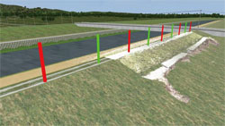
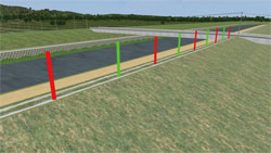
Supported Projects Types
- Although
this plugin abides to the regulations set by the Japanese Ministry of
Land, Infrastructure, Transport and
Tourism's 「(3)土木工事施工管理基準及び規格値」 (lit. Infrastructure Civil
Engineering Management Criteria and Standards), the use of point cloud data is currently only limited to cut / embankment
projects, and some other earthmoving road projects.
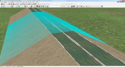
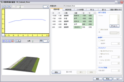
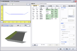
Design Cross Section
- Elements
that make up the Design Cross Section such as the linear shape
of
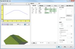
embankments or cuts cab be defined and edited inside UC-win/Road
directly via "Section Editing". If LandXML file is available, it is
even easier by merely importing the design data.
Work Progress Management Criteria and Standard Values
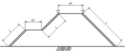
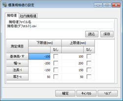
- Since this plug-in is primarily limited to earthworks, the measured elements
contain only the heights, widths, slope lengths, and thicknesses. Standard
values can be manually specified according to the project in question. This
can be a value defined by the regulation or by a custom corporate standard
if necessary.
 |
|
 |
Measured
Elements |
Standard
Values |
| Reference
Height▽ |
-50 |
| Slope
Length L |
l<5m |
-100 |
| l≧5m |
Slope
Length -2% |
| Width
w1,w2 |
-100 |
|
|
 Setting
Standard Values Setting
Standard Values |
Work in Progress Cross Section
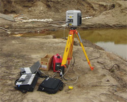
- To
obtain the work in progress tentative cross section, users can
use
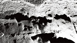
our 3D laser scanning service to retrieve the point cloud data and
ground surface TIN data. Since every measurement point can properly
create the tentative cross section, it is possible to obtain large
amount of accurate data in a very short time.
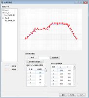 |
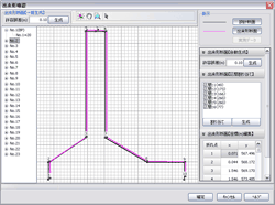
 Examining and Editing Cross Section Data Examining and Editing Cross Section Data |
Work Progress Management Report Formats
- Reports are created according to the formats
specified in the "土木工事共通仕様書" (lit. Civil
Engineering Common Specifications) by the Ministry of Land,
Infrastructure, Transport and Tourism. The following reports can be
generated:
| Format
No |
Name
of Format |
| Format
31 |
Work Progress
Management Diagrams |
| Format
80 |
Quality and WIP
Quality Management Table |
| Format
81 |
Measurement
Synoptic Table |
| Format
82 |
Measurement Result
Table |
| Format
84 |
Work Progress
Management Chart
(Process Capability Chart) |
| Format
85 |
Frequency Table |
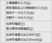
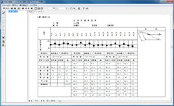
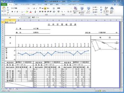
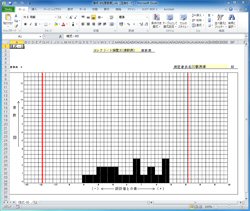
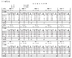
- The Work Progress Management documents can either be printed directly,
or exported into an Excel file (supports Excel 2000-2010). Documents can
therefore be quickly edited and adapt to other formats if necessary.
 |
 |
 Print Preview
(Format 31) Print Preview
(Format 31) |
 Excel
File(Format 31) Excel
File(Format 31) |
 |
 |
 Excel File
(Format 85) Excel File
(Format 85) |
 Measurement
Synoptic Table Measurement
Synoptic Table |
Use in Conjunction with Photog-CAD
- Photog
-CAD(by Japan Construction Information Centre)is a software that allows
the conversion of disaster site photos taken by a standard digital
camera into 3D models, which is then further processed into cross
section maps and evaluation documents. The Work Progress Management
plugin recognizes the ground surface TIN data generated by Photog-CAD,
and can be imported into UC-win/Road. Thus, instead of using 3D laser
scanners, it is also possible to use a digital camera.
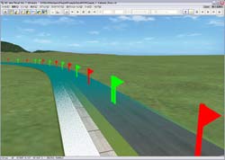
Sample Pictures
 |
|
 |
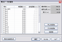
 Work Progress Data
Setting Work Progress Data
Setting
- Measurement Points |
|
 Work Progress Data
Setting Work Progress Data
Setting
- Point Cloud Files |
 |
|
 |
|
 |
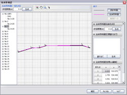
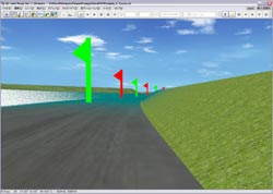
 Embankment Embankment |
|
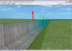
 Embankment-WIP Cross
Section Embankment-WIP Cross
Section |
|
 Embankment-Design
Cross Section Embankment-Design
Cross Section |
 |
|
 |
|
 |
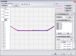
 Excavation Excavation |
|
 Excavation -WIP
Cross Section Excavation -WIP
Cross Section |
|
 Excavation-Design
Cross Section Excavation-Design
Cross Section |
 |
|
 |
|
 |
 Retaining Wall Retaining Wall |
|
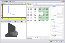
 Retaining Wall-WIP
Cross Section Retaining Wall-WIP
Cross Section |
|
 Retaining
Wall-Design Cross Section Retaining
Wall-Design Cross Section |
|
|


