| UC-win/Road Ver.5.1 |
||
| 3D real time VR software package |
| Price: $5,800-(New license purchase)/Revision up free Released in January 2011, |
Simulation |
| New Products | ||||||||
|
||||||||
| Improved vehicle dynamics model |
| Increased realism in the representation of vehicle dynamics The driving simulation in UC-win/Road was improved through the refined vehicle dynamics model (a four-wheeled vehicle). Increased realism in the representation of vehicle dynamics has been enabled through the implementation of models ranging from whole vehicle movement to engine and power train system from the engine to the wheels. Following situations can be visualized with the new version of the software. Representation of understeer and oversteer is possible. This is a phenomenon where a car does not turn in the same way unless the driver input greater steering compared with a low-speed driving. (Figure 1), when the car is running at high speed,. Cars may not be able to make a turn when the driver turns the steering wheel when the speed is too high and it is not possible to drive safely.
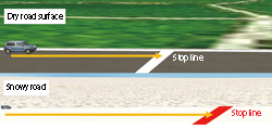
This is a phenomenon where rear wheels slip while making the turn and tends to cause an abrupt, sudden turn. The representation of vehicle’s slip to the front and the back direction has been made possible. It is a phenomenon caused by a sudden start or a sudden brake on a slippery road surface. Acceleration performance is decreased by the slip and the result is a longer braking distance. You can set the coefficient of friction of the road surface and can reproduce various road surface conditions. Now you can configure vehicle’s driving properties on snow, water and ice, as well as on a dry road surface condition. (Figure 2) In addition, you can set the differences - the grip between white line and road surface too. As you can set the coefficient of friction for each vehicle according to the setting of the road surface, the characteristic of each vehicle can be reproduced in detail. In reality, you have to run in consideration of regulation speed, the road surface conditions and the characteristic of the car. The newly released function allows driving in a condition which is close to the real driving conditions by reproducing the tire slip.
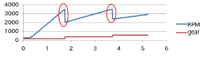
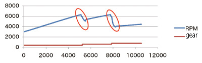
Gear change by manual operation is now possible together with an improved model of the automatic gear change. Smoother change of the engine number of revolutions is realized as compared to the existing versions.
We have made enabled the calculation of revolving speed for each of the wheel. It allows us to represent the different revolving conditions of the outer and inner wheels, as well as locked wheels and are skidding on the road surfaces when the strong braking is applied. A reverse run has been enabled in the vehicle dynamics model. You can choose from a variety of models from the existing dynamics model and newly developed models. Models can be selected according to users’ needs, such as models for inexperienced users or experience simulator for children. |
||||||||
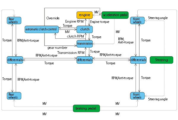
| Structure of vehicle dynamics model |
| The followings parts are modeled in UC-win/Road. Engine torque is calculated based on the operation of the accelerator pedal. Acceleration timing and engine braking is represented with the biggest and the smallest torque and the two curves. In UC-win/Road 5.1, you can edit the curve of the smallest torque (engine braking). Clutch is a device to connect the axis of transmission with the axis of engine. It conveys torque from the engine to the transmission partially or fully according to the state of the clutch. When the clutch is cut-off, the engine revolves freely. On the contrary, the revolving speed of the wheel is associated with that of the engine when the clutch is connected. Therefore, the power conveyed to the transmission and the number of revolutions is calculated according to the state of the clutch. Engine power is conveyed to the next differential gearing with a certain ratio. Each gear inside the car can be reproduced. It is a module to control the state of the clutch and choosing the gear. A behavior model of the cars in UC-win/Road is close to that of a car with a manual transmission; however, an automatic clutch device has been implemented to reproduce an automatic car. It controls the clutch and the transmission of a manual transmission car automatically. In addition, users can operate a shift-up and the shift-down depending on the situation such as start, braking and normal driving. Differences between the speed of the inside wheel and that of the outside wheel occurs when a car makes a turn at the curve. Differential gearing is used to distribute one torque output by the engine and allows each wheel can at different speed. More torque is transmitted to the wheels with lesser resistance. When a car make a turn, the outside wheel advances faster than the inside wheel. As a result, because an outside wheel has little resistance from the road surface causes, the torque is conveyed a lot to an outside wheel. The left side wheel are driving on the frozen surface while the right is on the dry one, the left wheels will slip and revolves faster. The number of differentials differs depending on car types. For the transmission of engine torque both to front wheels and to rear wheels(in 4 wheels drive car), a differential is used to distribute torque to front wheels and rear wheels and 2 differentials are used to distribute to right and left at front and rear. For the transmission of engine torque only to front wheels or to rear wheels, only one differential is required. Transmitting torque to the front wheels is called “front-front(FF)” and to the rear wheels is called “front-rear(FR)”. Torque produced by the engine reaches the wheel through transmission devices. As well as the torque, braking torque and torque by the friction of the road surface turn a wheel at a certain speed. In addition, the power exists which is caused by apply on the road surface by this revolutionary wheels. Seeing from a road surface (seeing from the outside), road surface applies power to each wheel and the power reaches and moves the vehicle. If the power of the right and the left is different, opposite forces in equilibrium act and the car make a turn. You can set the position of the gravity center in UC-win/Road.Since the gravity adapted to each wheel changes depending on the change of the position, the frictional force of the wheel changes accordingly. For example, the distinction of the FR (front-rear) car and the MR (middle-rear) car is possible by changing the position of the gravity center. Engine is placed at the front of the car in FR, and placed at the center in MR. Because an engine is heavy, the position of the gravity center of the vehicle changes by the position where the engine is placed.
|
| Setting items in detail |
This is a curve to define frictional force occurring between tires and road surface. There are a lot of physical models for the calculation of the frictional forces to vehicles, which reproduces the sliding of tires ranging from complicated finite element method to relatively simple coulomb friction law,. The curve of the coefficient of friction by the slip ratio (Slip Ratio) is used in UC-win/Road. You can edit this curve and set the condition of various road surfaces because it is used as an attribute of the road surface. The slip ratio expresses differences between speed and surface speed of the tire outside of the vehicle. The expression of the slip ratio is as follows:
Usually, when the value is [-0.1. 0.1.], cars are not supposed to slip and a coefficient of friction becomes linear depending on the slip ratio. The value of the slip ratio is bigger than 0.1, the car is accelerating while slipping and the coefficient of friction becomes the approximate constant value. In addition, when the value is smaller than -0.1, the car is slowing down while slipping and the coefficient of friction becomes the approximate constant value (Figure 6).
You can set the biggest torque and the smallest torque of the engine (Figure 7). In addition, the moment of inertia of the engine is necessary to calculate the revolution speed of the engine. You can also set the moment of inertia of the engine.
You can set the ratio of each gear and the ratio of the reverse gear by setting the gearbox. You can choose the mode of the gear change from automatic to manual. You can choose the constitution of the differential gearing to set how the engine power reaches the wheels. Representing the FF or FR of 2WD, or 4WD is possible. You can set the final drive ratio and transmission performance with this parameter. This is a parameter to use for the calculation of the turn of the car. If the moment of inertia becomes big, the reaction of the car becomes slow. You can set the position of the mass (position of the engine, position of the passenger) by setting the position of the gravity center. You can now set the ratio of the brakes stress of front wheels and rear wheels. This is a parameter used for the calculation of the number of revolutions of the wheel by moment of inertia. If the moment of inertia becomes bigger, the reaction of the wheel becomes slower. You can also set friction coefficient caused by the rolling wheels and wheel radius. |
| Improved crash representation |
| In the previous versions, when the car hit the road-side fence, the car
returned to the carriageway in the same driving direction and slowed down.
In the new improved version of the program, a process was implemented to
apply force to the car and hence, the car does not go out of the road shoulder
when the car touches the fence. This allows the checking of the suspension
work and the representation of the effect of the car's hitting the wall,
because the force is applied without making a sudden change to the driving
direction and speed. We will improve this process and develop the judgment
of the contact with other vehicles. |
| Road surface property |
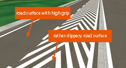
Friction coefficient is necessary to calculate the friction which occurs between wheels and road surface, For the calculation, the curve of friction coefficient by slip ratio is used and this curve is set as an attribute of road surface. Only the friction ratio must be set for each vehicle. The final friction coefficient is calculated by multiplying the friction coefficient curves of the current road surface by the friction ratio of the vehicle. Settings of the road surface can be set for an individual texture which is used for the road cross section. You can obtain fine effects by setting the texture of lines and white lines of each traffic lane of the driving carriageway. (Figure 8). In future development, we are going to make a vehicle to drive along the surface other than that of the carriageway.
|
| Tunnel lighting function |
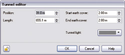
| With UC-win/Road 5.1, you can now set lightings in the tunnel space (Fig.
9). You can set the color and intensity of illumination for each tunnel.
All you have to do is to apply the settings to one item and the intensity
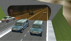
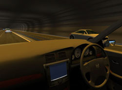
of light varies according to the brightness of the color. With the tunnel lighting functions, it has become possible to distinguish between tunnel lighting and the external solar lighting, which implied increased realism in visual representations. The illumination in the tunnel is applied to the vehicle driving inside the tunnel and road-side facilities. Representation of the vehicle's cockpit and the entrance of the tunnel of have been improved especially.(Fig. 10, 11). However, in this version, if you place other models in the tunnel, the tunnel lighting effect does not work.
|
| VISSIM |
| UC-win/Road 5.1 can now load and visualize the result of traffic flow analysis
of VISSIM. VISSIM, a traffic simulation software developed by PTV, is an
integrated solution which can combine pedestrian and vehicle traffic.(URL:
http://www.vissim.de). Using Micro Simulation Player, users can read ANI.TXT file of VISSIM into UC-win/Road. After reading the results of the simulation, set the position to display the simulation result and choose models to show vehicles and pedestrians. Finally, you can operate the reproduction of the traffic simulation result like a movie file and can check the traffic situation in 3D space (figure 12).
|
| (Up&Coming 2011 New Year Issue) | ||
 |