| When you create a 2D frame model in a 3D space, conduct an analysis, and
export its report, a figure of bending moment in bird's-eye view like the
figure 1 is created. In this topic, we explain how to easily change it
to a drawing of bending moment in plan view. Here we create a 2D frame
model on the X-Y plane. Select "Load Cases" for Load Type in
Analysis Settings in advance. |
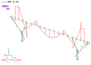 |
| Fig.1 Drawing of bending moment in bird's-eye view |
Operation 1
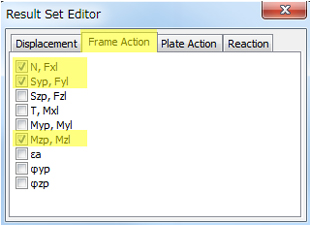
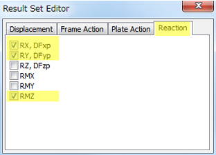
Select components focusing on the 2D analysis result. Go to "Report"
Ribbon - "Result List" - "Load Case", and configure
Displacement, Action, and Reaction (Fig.2, 3, 4).
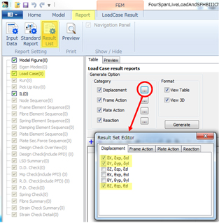 |
| Fig.2 Not to output unnecessary components (Displacement) |
 |
 |
| Fig.3 Not to output unnecessary components (Action) |
Fig.4 Not to output unnecessary components (Reaction) |
Operation 2
Press "Generate" button (Fig.5). When the result has many load
cases, a lot of lists are created.
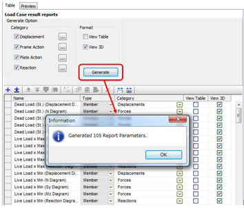 |
| Fig.5 Auto-creation of multiple load case reports |
Operation 3
Select multiple report lists created automatically (Fig.6). Hit the down
arrow key while pressing Shift key. Clicking on the list while pressing
Ctrl key behaves in the same way. All lists will be selected when hitting
A key during pressing Ctrl key.
Operation 4
Click "Camera" in Navigation on the right side, and select "Side
View" for Camera Position Type (Fig.6).
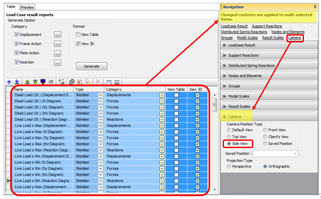 |
| Fig.6 Camera position setting of multiple lists |
| With the operations above, the result model drawing is displayed in side
view (2D plane) (Fig.7). This is useful to change a lot of load cases at
once. Report lists increase by every click on the generate button shown
in the figure 5. If you want to do it over again, please delete the existing
lists first and generate new lists. |
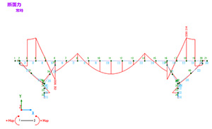 |
| Fig.7 Drawing of bending moment in side view |
|

