Issue and Reason
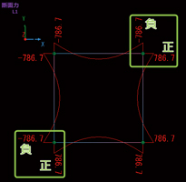
Although the bending moment drawing looks like that it has no problem,
sometimes the values at the corner of the rigid-frame structures have different
signs (Fig.1). The figure 2 is an example of arranging a box structure
on the X-Y plane of whole coordinate system.
 |
 |
| Fig.1 Different signs of bending moments at the corner |
Fig.2 Default setting of the main axis yp (reason of this issue) |
Rules of section force sign
The sign of section force is determined for the main axis coordinate system
xp-yp-zp (Fig.3).
- Mzp is positive when the beam bends to the negative side of the yp axis.
- Myp is positive when the beam bends to the negative side of the zp axis.
Why does the bending moment drawing have no problem?
The sign of section force value is determined according to the rule above.
As for a section force distribution drawing, however, positive moment drawing
is drawn on the opposite side of the +yp axis regardless of the position
of the i edge and j edge.
|
|
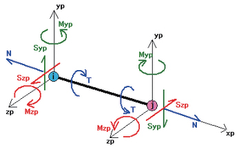 |
| Fig.3 Signs in section force drawing |
|
How to deal with
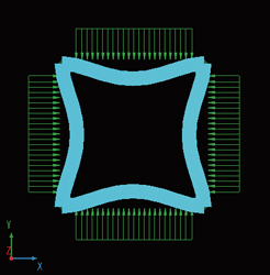
To solve this problem, configure that the moment becomes positive when
all of top slab, bottom slab, left wall and right wall bend inward.
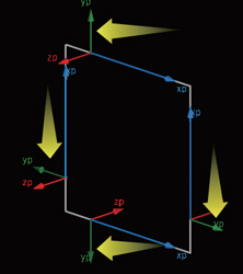
To configure this, make the yp axis face outside. Access the setting form
from the Navigation "Nodes & Elements | Frame Element Definitions
| Frame Elements", the row of the LA coordinate System.
If it is set as below, the signs of moments at the corners become the same.
(Fig.6).
 |
 |
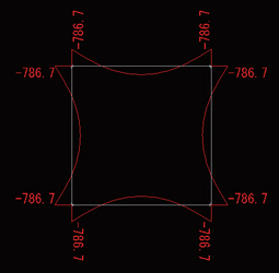 |
Fig.4 When inward-focused bending occurs,
it is a positive bending moment. |
Fig.5 Make the main axis yp face outside |
Fig.6 The intended bending moment drawing |
|

