Positive and negative codes generating on a spring element are decided
by the relationship between the orientation of the element coordinate system
and the i/j end node of the spring element. Note that it is not only determined
by the orientation of the spring element. Spring element codes can be decided
as follows:
Firstly, subtract the i-end nodal displacement from the j-end nodal displacement.
The result is the value in the global coordinate system based on the i
end.
Next, coordinate conversion is performed on the value to the element coordinate
system. The result is the value in the element coordinate system based
on the i end.
The sign of 2 matches that of the spring characteristic.
Even if you do not strictly apply the rules above, you can easily test
using the model you are creating.
It is a method of loading a load experimentally unidirectionally so that the spring element is clearly in a compressed state (or tensile state).
Example: Model of the spring element that backside soil resists against
abutment
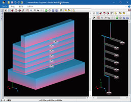
- Select the model with the spring element that backside soil resists against
abutment (Fig.1).
- Horizontal seismic intensity load is applied as the experiment load in
the whole X axis direction (Fig.2). Set the sequence load to 0.01, and
the number of applications to 100 (Fig.3). By dividing the load weight
into 100 parts, it is possible to easily confirm the response result of
the spring element after analysis.
 |
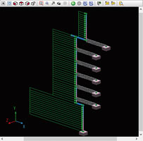 |
 Fig. 1 Model of the spring element that Fig. 1 Model of the spring element that
backside soil resists against abutment |
 Fig. 2 Unidirectional loading Fig. 2 Unidirectional loading
experimentally |
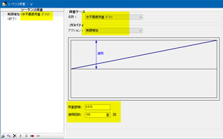 |
 Fig. 3 Setting of loading 100 times in increments of Fig. 3 Setting of loading 100 times in increments of
one hundredth |
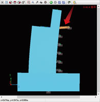
- As you can see from the displacement chart, the frame is deformed on the
back soil side as expected (Fig.4).
- Focus on the spring element indicated by the arrow in the figure 4.
- Check the time history result of the spring element (Fig.5). It can be
expected that the response will be produced on the side with rigid because
the rear soil resists. Positive direction bilinear is set in this spring
characteristic, and it is certain that it is responding on the positive
side with rigid.
 |
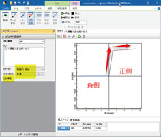 |
 Fig. 4 The body deforming to the Fig. 4 The body deforming to the |
 Fig. 5 Response of the rear soil Fig. 5 Response of the rear soil
on the resisting side |
- Thus, it can be judged that the setting of nonlinear spring element is
right.
In this example, the modeling is incorrect if you obtain the result that
the response is produced on the negative side of the spring characteristic.
In that case, please make one of the following changes. Note that if you
do both modification, the result will remain the same.
- Reverse the positional relationship between the i and j end of the spring
element.
- Reverse the positive and negative of the spring characteristic (using negative
bilinear).
|

