

A 2D linear elastic frame/truss structural analysis product.
Engineer's Studio® 2D Ver.4
Initial Release: 2009.05.19 / Latest Ver.: 2026.03.26
- Engineer's Studio® 2D
- USD2,550
- Beam Model Live Load Analysis Option
- USD200
- Japan Civil Codes Uniaxial Section Design (Partial Factors method) Option
- USD1,570
- Japan Civil Codes Uniaxial Section Design Option
- USD1,001
Related Products/Services: Engineer's Studio®
Program Overview
Engineer's Studio® is a 3D material and geometrical nonlinear FEM analysis program that Forum8 developed the pre / post / solver in house.
Engineer's Studio 2D is a 2D linear elastic frame/truss analysis product that has been developed from the parent libraries to meet these needs. It is the successor to the well known product, UC-1 FRAME (In-plane). The user interface is very similar to the 3D parent product Engineer's Studio®. Hence users can invest in learning this new CAD style interface and rest assured that if required, these skills will facilitate the move to 3D analysis in the parent product.
- Analysis tool specialized in 2D in-plane frame/truss analysis.
- Material and geometrical linear static analysis.
- CAD style intuitive user interface for creating nodes and elements graphically.
- Full table editor support for all data creation and editing.
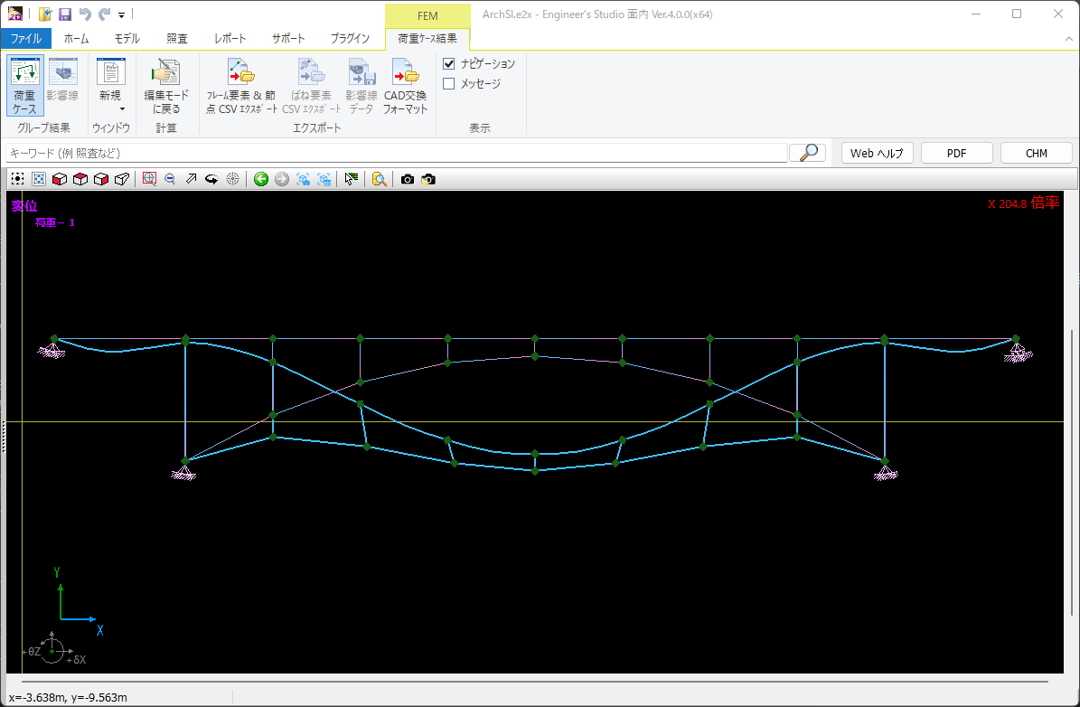
▲Displacement chart image of arch bridge model data
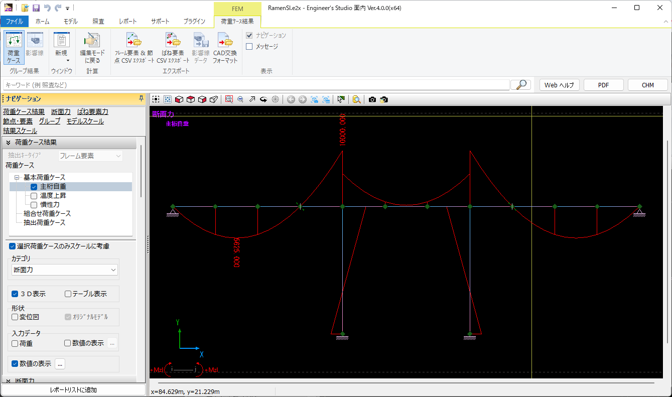
▲Displacement figure of rigid frame bridge model data + section force chart
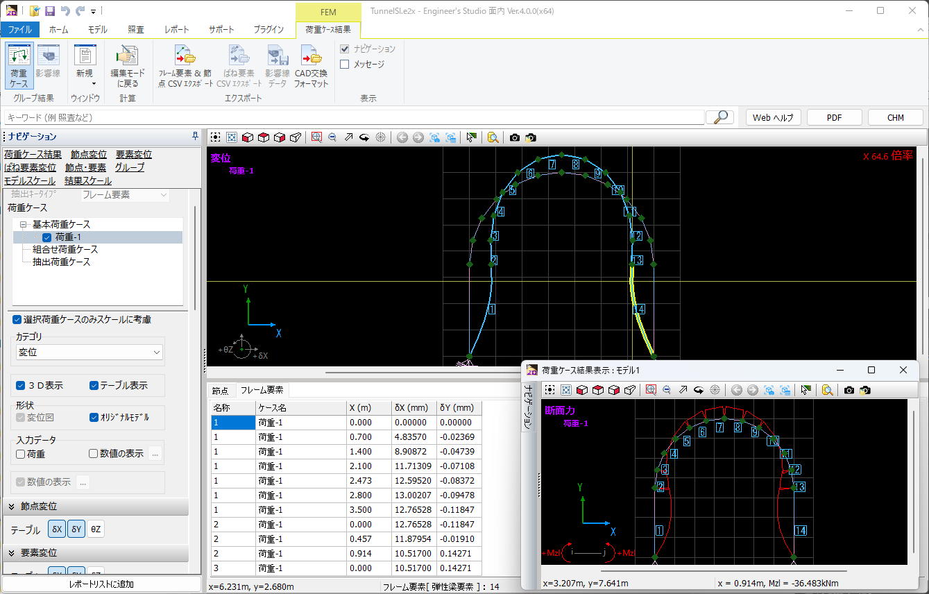
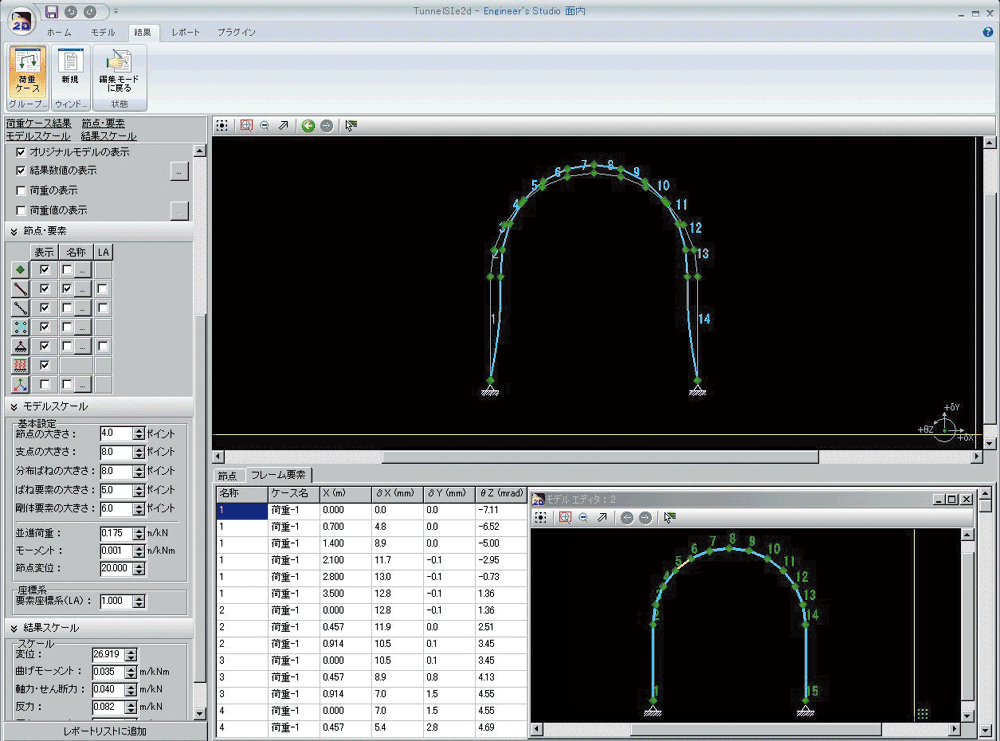
▲Tunnel model data structure + displacement map

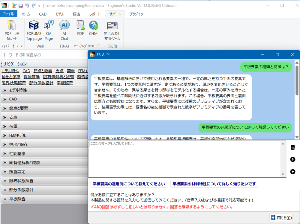
"F8-AI® UC Support"
AI chat helps your design work
We provide solutions within the product itself for input operations and explanations of computational theory, eliminating the need to contact support desk.
Support for multiple languages and voice input allows foreign engineers to use AI chat in their native language.
Ver.4.0.0 Revised Contents <Released on March 26, 2026>
- Compliant with the 2025 Specifications for Highway Bridges
- F8-AI® UC Support
- Support for high-resolution display
- 64-bit version support
Functions and Features
With its intuitive CAD-style input and editing, you can create and modify models more easily. There are calculation functions and convenient model creation support features that are not included in UC-1/FRAME (2D).
Features of the program
-
- Creation of continuous beam elements and positioning of nodes (element resizing), frame elements, spring elements, and rigid body elements (*1)
- Search function (node, frame, spring, rigid body) (*1)
- Displays / hides in group unit. Calculates the max / min bending moment (*1)
- Automatic creation of dead loadcase and horizontal seismic load
- Calculates material displacement (*1)
- Supporting points can be changed in the selected state. Loads will be kept even when the element is re-divided. (*1)
- Spring element can be connected to the main node of rigid element. Multiple elements can be connected to rigid element. (*1)
- Moment loads can be input to beam elements supported by distributed springs. (*1)
- Internal force like prestress can be input to beam elements supported by distributed springs. (*1)
- UC-1 FRAME (in-plane) (.fsd), (.$o1) data files can be imported.
- Mmax between the focused points of frame element is automatically calculated against basic loadcase / combined loadcase.
* (*1): These functions are not supported in UC-1 FRAME (in-plane).
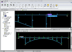
▲Arch bridge model data structure diagram
Dual-screen display (dockable)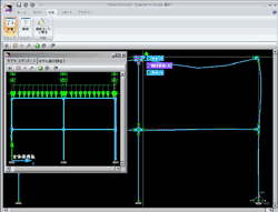
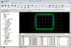
▲BOX culvert model data load diagram +
Displacement map images (2 images)
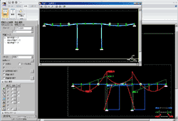
▲Displacement figure of rigid frame bridge model data + section force chart
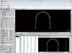
▲Tunnel model data structure + displacement map

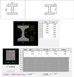
Inputting section shape
-
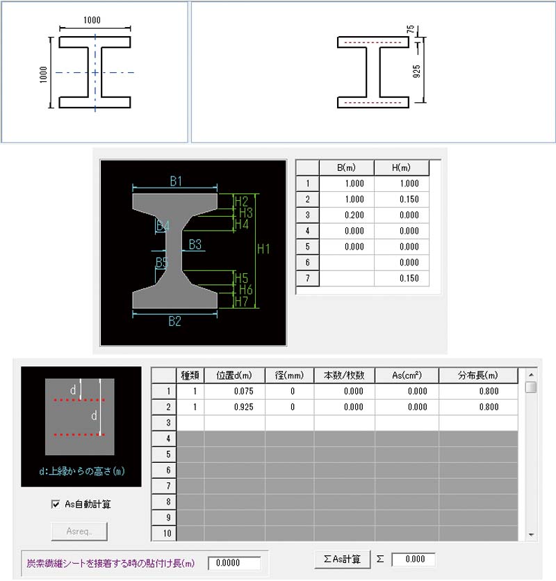
Frame calculation can be performed after entering the section shape and auto-calculating section constant. Supported section shapes: rectangle, oval, circle, I beam, T beam, W T beam, box, and hollow sections with circular openings.
▲Inputting section shape
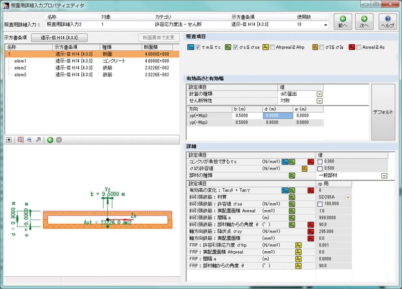
and reinforcing bar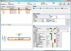
▲Input screen of section calculation
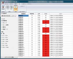
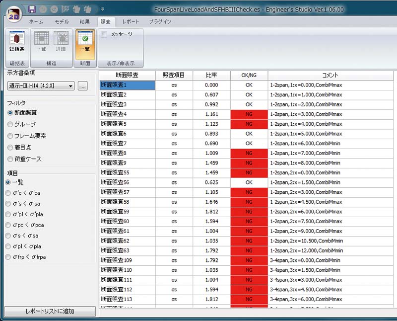
▲List of section calculation result
Elements
-
- Euler beam element.
- Truss element (available when both ends are pin in the Element Boundary Conditions)
- Euler beam on elastic spring element (Defines fixed, free, or spring relationships between two nodes in each degree of freedom.)
- Rigid body element
Supports
-
- Node supports.
- Multiple node support cases.
- Multiple spring boundary support cases.
- Support cases are specifiable per load case.
Load
-
- Translational and Moment node loading
- Forced node displacements
- Element distributed loading
- Element point loading
- Basic load cases, combinations, and envelopes
Japan Civil Codes Uniaxial Section Design (Partial Factors method) option
-
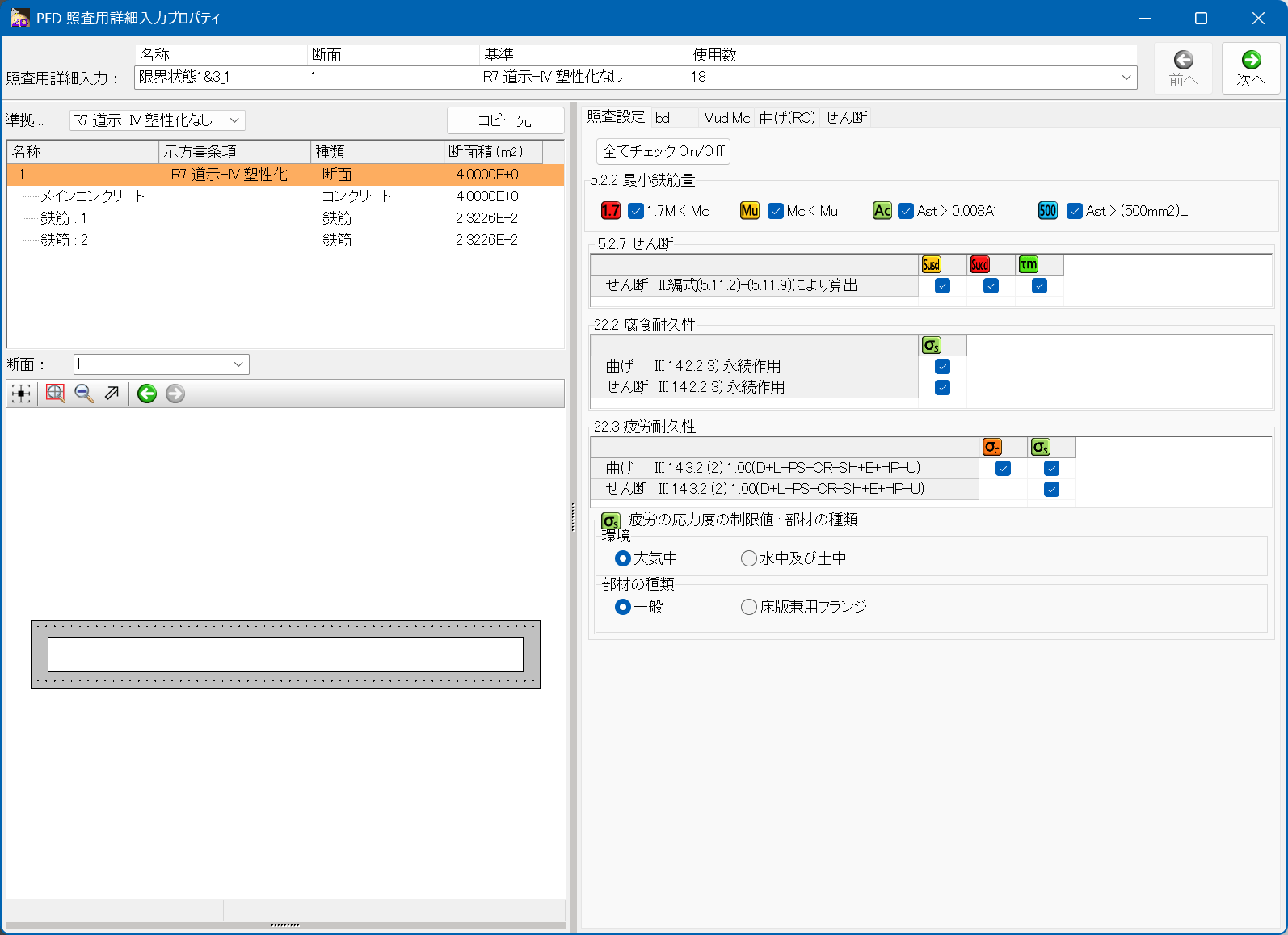
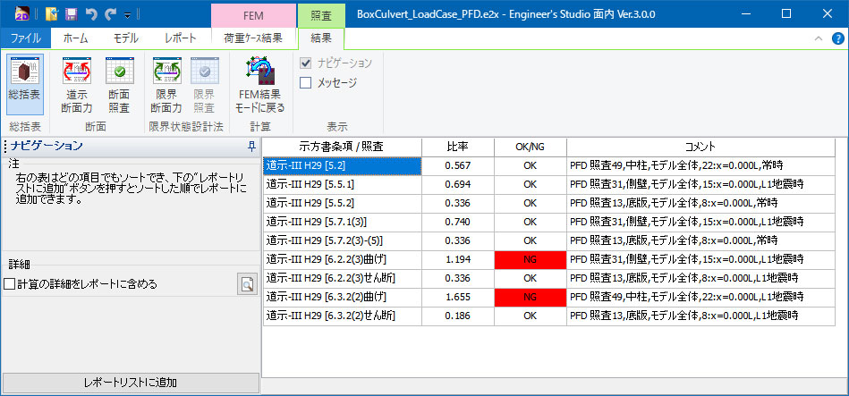
A separately sold option "Japan Civil Codes Uniaxial Section Design (Partial Factors method)" according to the 2017/2025 Specifications for highway bridges has been newly added. The bending stress test, bending strength test, and shear strength test can be conducted by the partial factors method.
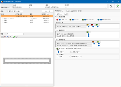
▲Example of an input screen
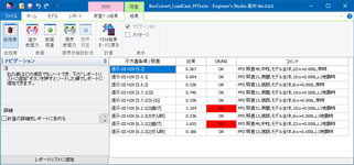
▲Example of a result screen (summary table)
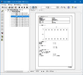
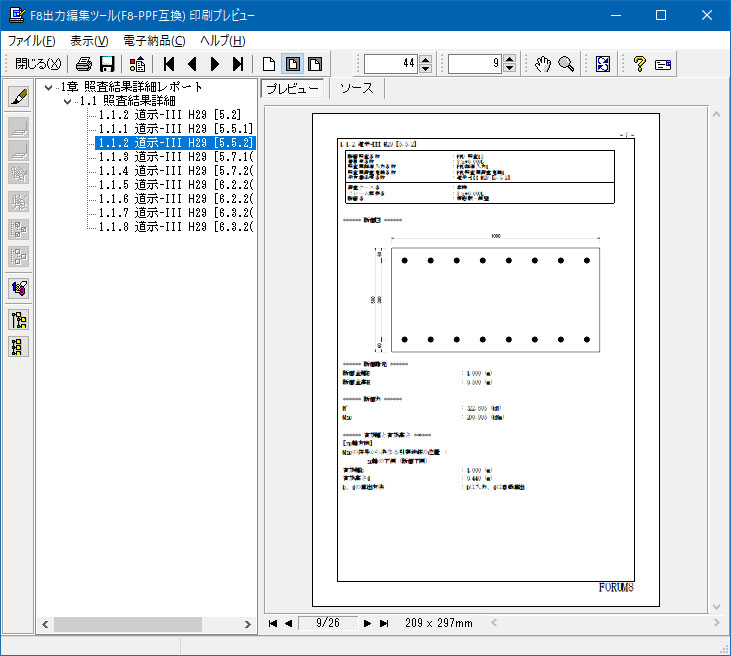
▲Example of report output
(Detailed results)
Feature Comparison: Engineer's Studio® 2D, UC-1/FRAME (2D)
Flow of frame analysis
-
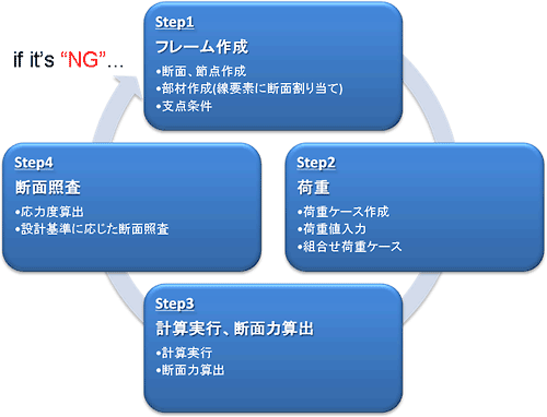
Engineers need to repeat the steps above until all checks pass.
Enhanced analysis functions
-
- Calculation of member displacement
- Possible to place spring elements at the main nodes in rigid elements
- Multiple elements may be connected to rigid elements
- Moment loads can be applied to distributed spring beam elements.
- Element internal forces, such as prestress, can be applied to distribution springs beam elements.
Applying moment loads to distribution spring components
-
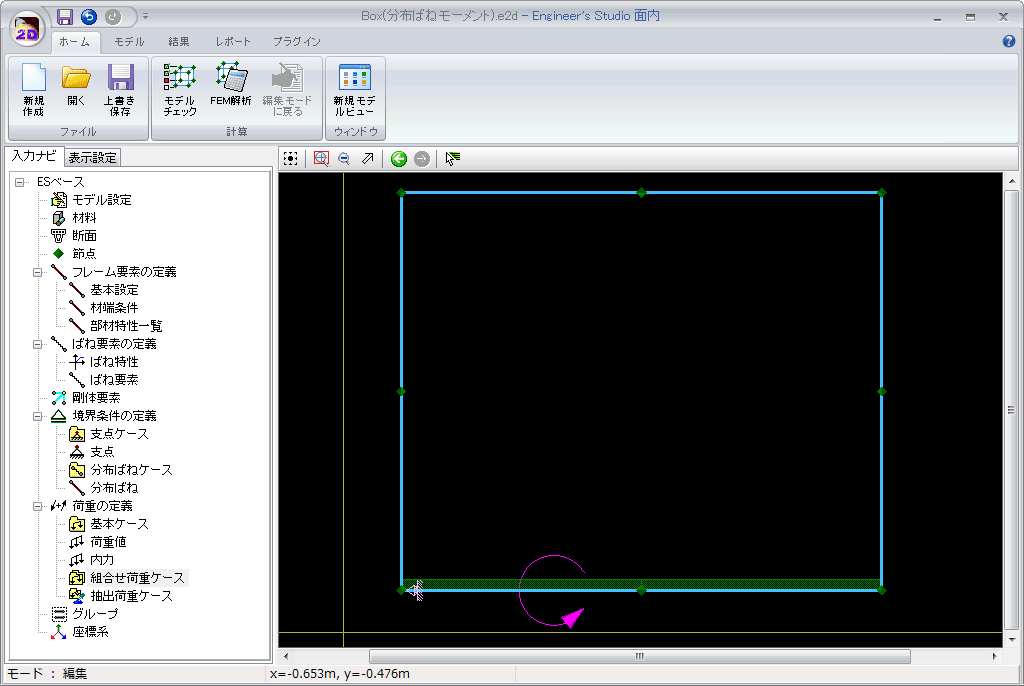
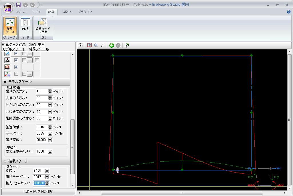
Example: Applying moment loads to arbitrary positions of a BOX culvert base.
▼ Load
▼ Shear force diagram
In UC-1/FRAME(In-Plane), it was necessary to create an extra intermediate node and apply a node moment load. This is not required in Engineer's Studio® 2D.
Nodes for load are not required any more because moment load can be input to distributed spring material in the Engineer's Studio® 2D.
Comparison with previous products
-
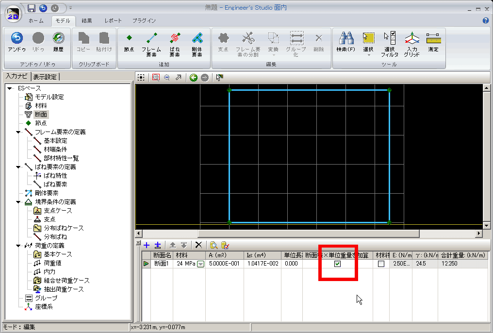
- Enter the cross-sectional area and the second moment of area.
- Enter the cross-sectional area and the second moment of area.
- Specify materials.
- The auto-generation of dead loads is available by checking "Add section area x unit weight"
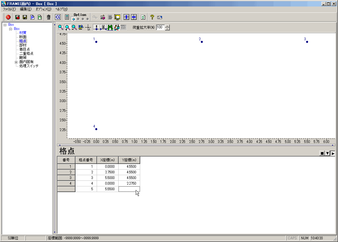
- Enter coordinate values for all nodes.
- Enter only the main nodes.
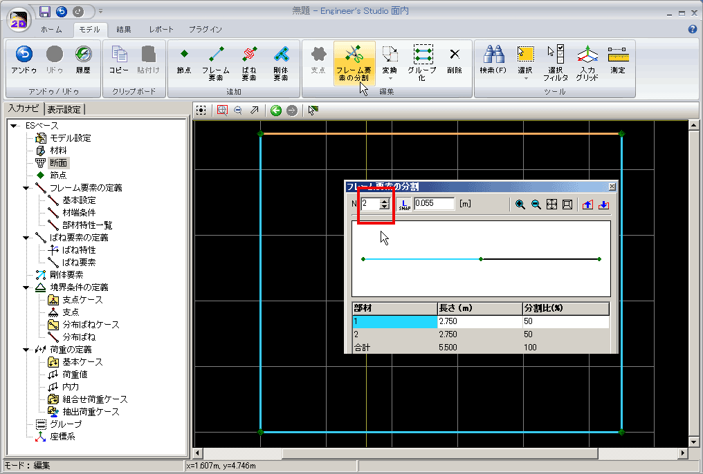
- Auto-generation of the middle nodes is more easily achieved by dividing beam elements after creating them later. At that time the individual member lengths can be controlled.
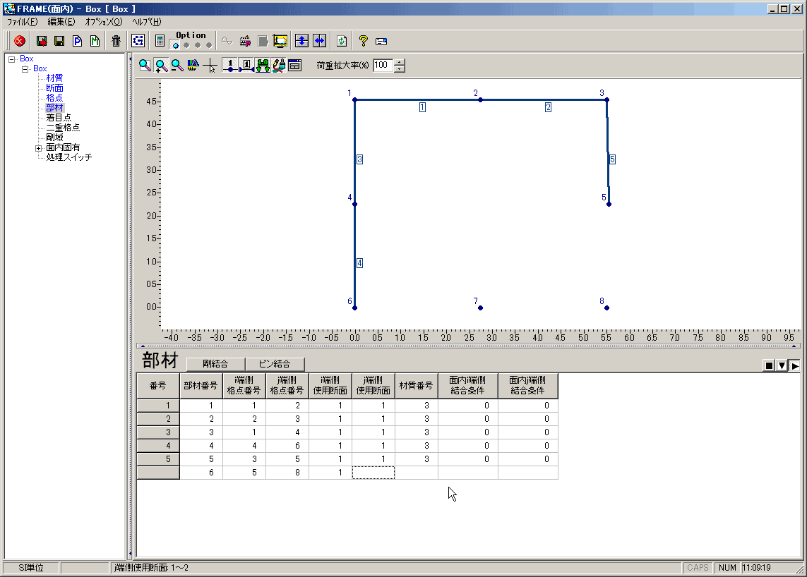
- Create line elements by specifying two nodes in the table editor after setting up all nodes.
- Assign section references to all members.
- Select sections, click prepared nodes, and create beams like drawing frames.
- Possible to undo during commands.
- Enter node numbers to set supporting point condition and supporting point code.
- Not possible to process collective setting for multiple nodes.
- Select nodes to set supporting condition by clicking on them and select restraint conditions.
- Possible to apply the same conditions simultaneously to a set of selected nodes.
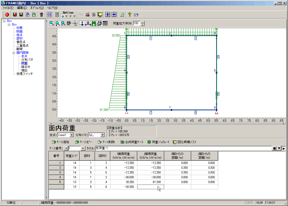
- Enter load code, intended members, and load values.
- Require retyping the load value after recalculating the load value at that position when the middle node is inserted.
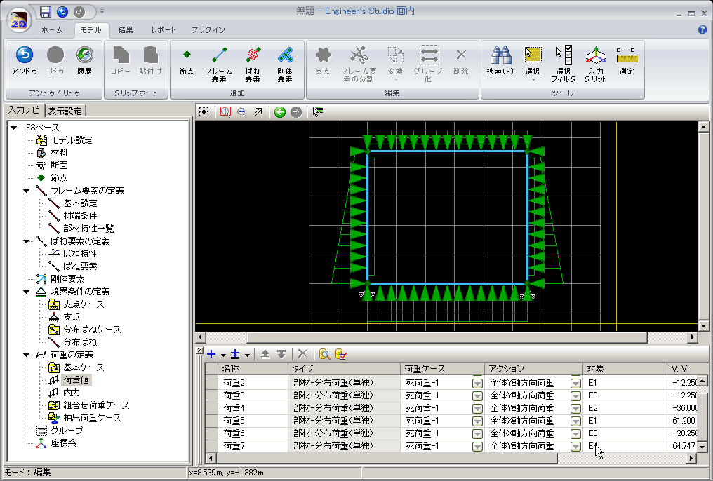
- Remembering load codes is not required. Select the load type from a list of names such as "point load" and "distributed load" and specify its direction and magnitude.
- Auto-interpolation of trapezoidal distributed loads is done when an element is split.
- Create a node at the 1/4 position from the deck slab. Reconnect i and j nodes.
- Calculate a load value at a newly added node (1/4 position) and setup.
- Divide sidewall elements using the "divide members" function.
- Connect the left and right intermediate nodes that are automatically generated by the division process using your mouse.
- The intermediate load value of the trapezoidal distributed load acting on the side wall is automatically interpolated.
1. Cross-section creation
UC-1/FRAME(In-Plane) Engineer's Studio® 2D 
2. Node input
UC-1/FRAME(In-Plane) Engineer's Studio® 2D 

3. Member creation
UC-1/FRAME(In-Plane) Engineer's Studio® 2D 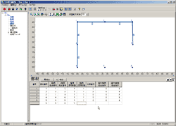

4. Support condition setting
UC-1/FRAME(In-Plane) Engineer's Studio® 2D 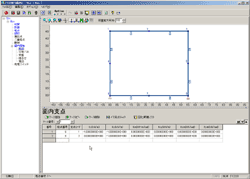
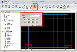
5. Load value input
UC-1/FRAME(In-Plane) Engineer's Studio® 2D 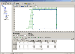
6. Data change, edit
Ex) Insertion of intermediate beam (1/4 height above the deck slab)UC-1/FRAME(In-Plane) Engineer's Studio® 2D 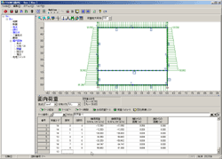



Comparison with previous products (time, in seconds)
-
UC-1/FRAME(In-Plane) [A] Engineer's Studio® 2D [B] Percentage Improvement: [B]/[A] Cross-section creation 15 25 1.67 Node coordinate input 63 *1 17 0.27 Member creation 54 16 0.30 Support condition setting 44 30 0.68 Load setting 240 228 0.95 Total of initial data creation 416 316 0.76 Data editing 340 40 0.12
*1: Only corner node coordinates were entered. The remaining middle nodes were entered when creating the elements.
*2: Values in the table represent seconds.
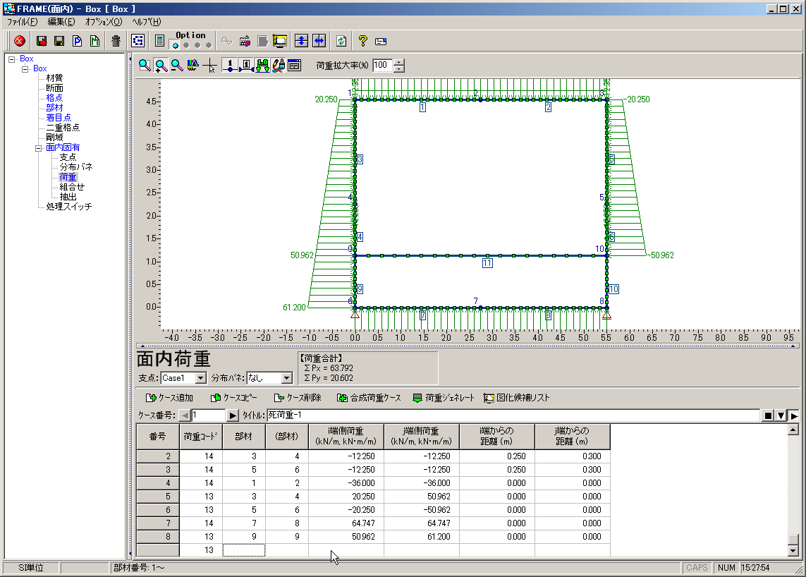
The model used in the above comparison is the BOX Culvert in-plane analysis shown in the picture on the right.
The self weight load case, 2 other load cases and combined cases of those are input.
Section properties and load value calculations are done outside the times quoted here. However note that the self weight load case is automatically calculated in Engineer's Studio 2D. Only the time of data entry and editing was compared.
The application operators used in this comparison have more than 5 years experience in this area.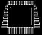
The percentage improvement in usage times is shown in the graph on the right.
The larger the model is, the greater the time difference becomes.
Time is cost and so especially for larger models, the cost saving achieved by using Engineer's Studio 2D compared to UC-1/FRAME (in-plane) is great.
This is especially noticeable when editing the model.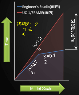
Product price
Subscription service, contract price
-
■Support information
-Software upgrade -Technical inquiry (Email, Tel)
-Download service -Maintenance and update notifications via email* We are sequentially making a transition from the maintenance-support service to [Subscription Service] from April 1, 2016 in order to enhance support for diverse product usage and to reduce license management cost.
■ Subscription Contract
Product Name Price of first year Price of subsequent years Engineer's Studio® 2D Ver. 4 USD2,550 USD1,275 Beam Model Live Load Analysis Option USD200 USD100 Japan Civil Codes Uniaxial Section Design (Partial Factors method) Option USD1,570 USD785 Japan Civil Codes Uniaxial Section Design Option 1,001 USD500 ■ Subscription Floating Contract
Paying 40% of the product price allows anyone to use the products on any PC anywhere in the world.
Product Name Price Price of subsequent years Subscription
FloatingEngineer's Studio® 2D Ver. 4 USD1,020 USD1,785 Beam Model Live Load Analysis Option USD80 USD100 Japan Civil Codes Uniaxial Section Design (Partial Factors method) Option USD628 USD1,099 Japan Civil Codes Uniaxial Section Design Option USD400 USD700 >>For more details about licensing options, please see here
■Pricing structure revision regarding changes to subscription rates
From July 1, 2025, the pricing structure for products equipped with F8-AI® Support was revised to 50% of the product price.
■■Subscription Contract Update Price for Users of Engineer's Studio® 2D Ver.3
For the initial contract renewal only, it will require both the price difference between Ver.3 and Ver.4 of the main product and the new subscription contract described above. * For contracts that include product options, the total charge will be calculated by adding the main product subscription cost and the product option subscription cost.
[Engineer's Studio® 2D Ver.4]
Feature Enhanced Cost
USD230
Feature Enhanced Cost for Floating License
USD322
[Japan Civil Codes Uniaxial Section Design (Partial Factors method) Option]
Feature Enhanced Cost
USD140
Feature Enhanced Cost for Floating License
USD196
Price of Rental License / Floating License
■Rental license : Short term licenses available at a low price
■Rental floating license : After web activation, anyone can use the products on any PC anywhere in the world.
■Rental access : You can increase the number of licenses you own and use these additional licenses for a specific period of time (1 month to 3 month) at your discretion. We will later send you an invoice based on your usage log. The advance application is 15% off of the regular rental license price. Please place an order from User information page.
*Rental / Floating Licenses were introuduced on September 2007 to enhance user experience and convenience of our products.
*Duration of Rental / Floating Licenses cannot be changed after starting these services. Re-application is required to extend the rental and floating license duration.
Rental license / Rental floating license
-
■ Rental License
Product Name 2 months 3 months 6 months Engineer's Studio® 2D Ver. 4 USD1,147 USD1,351 USD1,657 Beam Model Live Load Analysis Option USD114 USD134 USD166 Japan Civil Codes Uniaxial Section Design (Partial Factors method) Option USD706 USD832 USD1,020 Japan Civil Codes Uniaxial Section Design Option USD450 USD530 USD650 ■ Rental Floating License
Product Name 2 months 3 months 6 months Engineer's Studio® 2D Ver. 4 USD1,912 USD2,269 USD2,805 Beam Model Live Load Analysis Option USD192 USD228 USD284 Japan Civil Codes Uniaxial Section Design (Partial Factors method) Option USD1,177 USD1,397 USD1,727 Japan Civil Codes Uniaxial Section Design Option USD750 USD890 USD1,101
Academy price
An Academic License can be provided for educational purposes and used by teachers, lecturers, academic researchers, and students.
Academy price
-
Product Name Academy price Engineer's Studio® 2D Ver. 4 USD2,040
Operating environment
Operating environment
-
OS Windows 11 CPU Windows 11: Intel Core i5, 8th generation or later, recommended quad-core processor or higher Required memory (including the operating system) (Recommended) 2GB of RAM or more; *Note: This may vary depending on the size of the model and the number of analysis steps.* Required disk space The installation requires approximately 80 MB or more of space
The computational time required ranges from several megabytes to several gigabytes, depending on the analysis model and the number of analysis steps.Display (screen resolution) 1280x800 or higher resolution Input data file extension E2D File output Supports F8 output editing tools for file formats including TXT, HTM, PPF, DOC, DOCX, PDF, JTD, and JTDC Integration with other products <Loading>
UC-1/FRAME(In-Plane)
UC-1/FRAME Manager
SI compatible version, F8 (old product). SI compatible version, F8 (old product) data ($o1)
<Preservation>
UC-win/SectionRemarks A graphics card that supports OpenGL 2.0 is required
Confirmed list of compatible graphics cards
Order / Contact Us
Order / Contact Us
-
■Inquiries about UC-win/Road
Contact us from Sales inquiry or email to ist@forum8.co.jp or forum8@forum8.co.jp■Sales Office
>> Sales offices
Screen samples
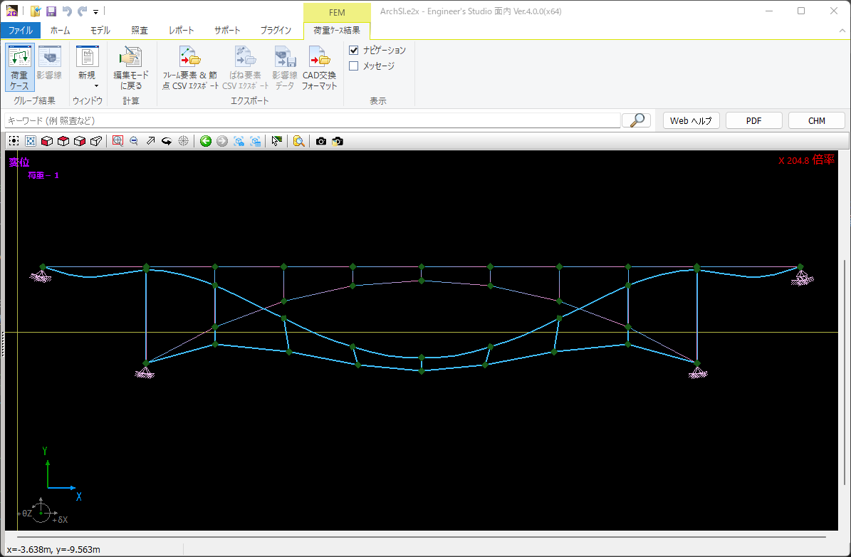
▲ Arch bridge model data displacement diagram
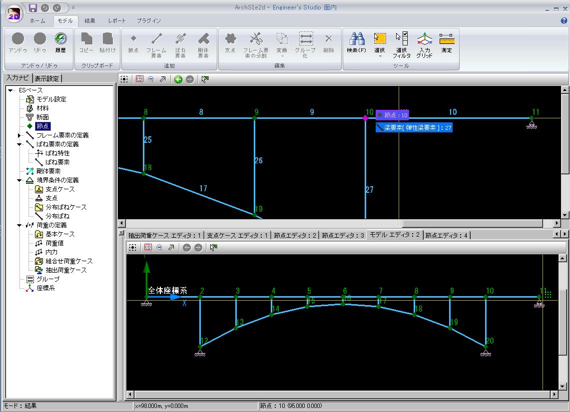
▲ Arch bridge model data structure diagram, displayed on 2 screens (dockable)
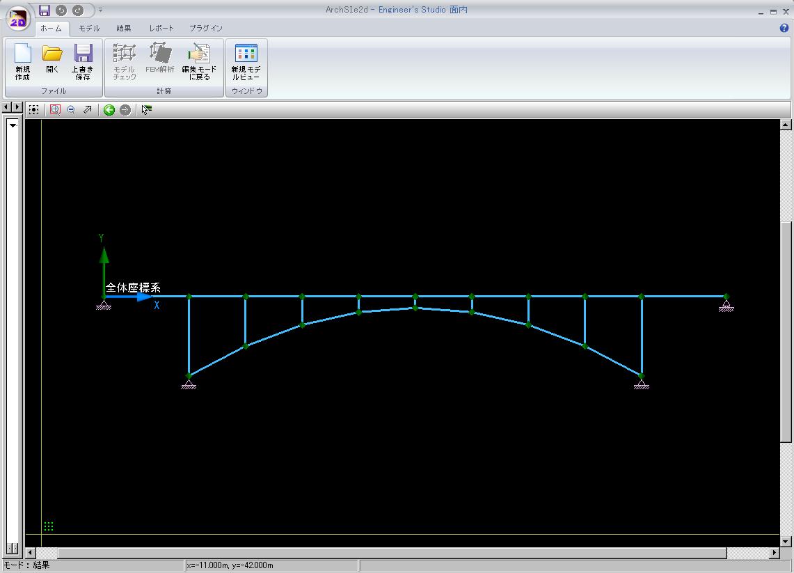
▲ Arch bridge model data structure diagram
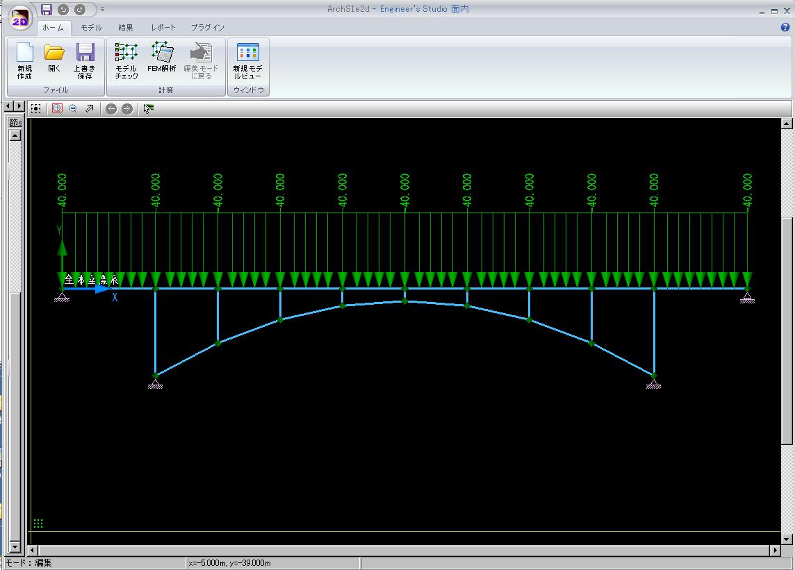
▲ Arch bridge model data load diagram

▲BOX culvert model data, load diagram +
Displacement map image (1 image)
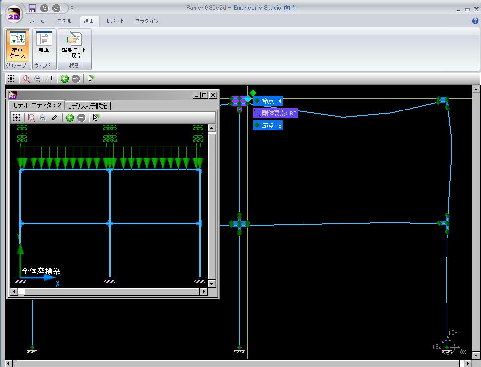
▲BOX culvert model data, load diagram +
Displacement map images (2 images)
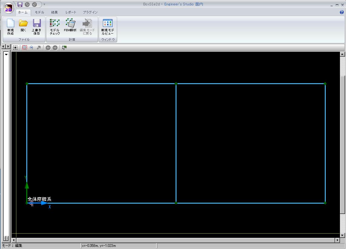
▲Diagram of the BOX culvert model data structure
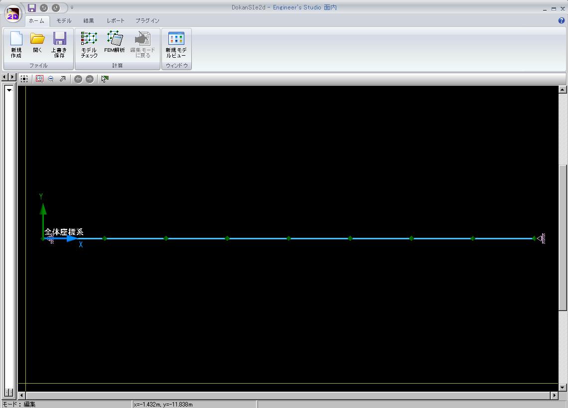
▲ Diagram of the data structure for a pipe model

▲Data structure diagram for a 2-layer ramen structural model
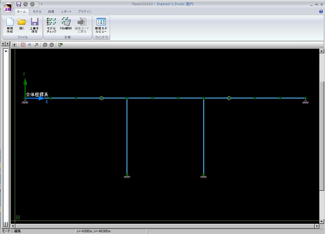
▲ Diagram of the data structure for the Ramen Bridge model
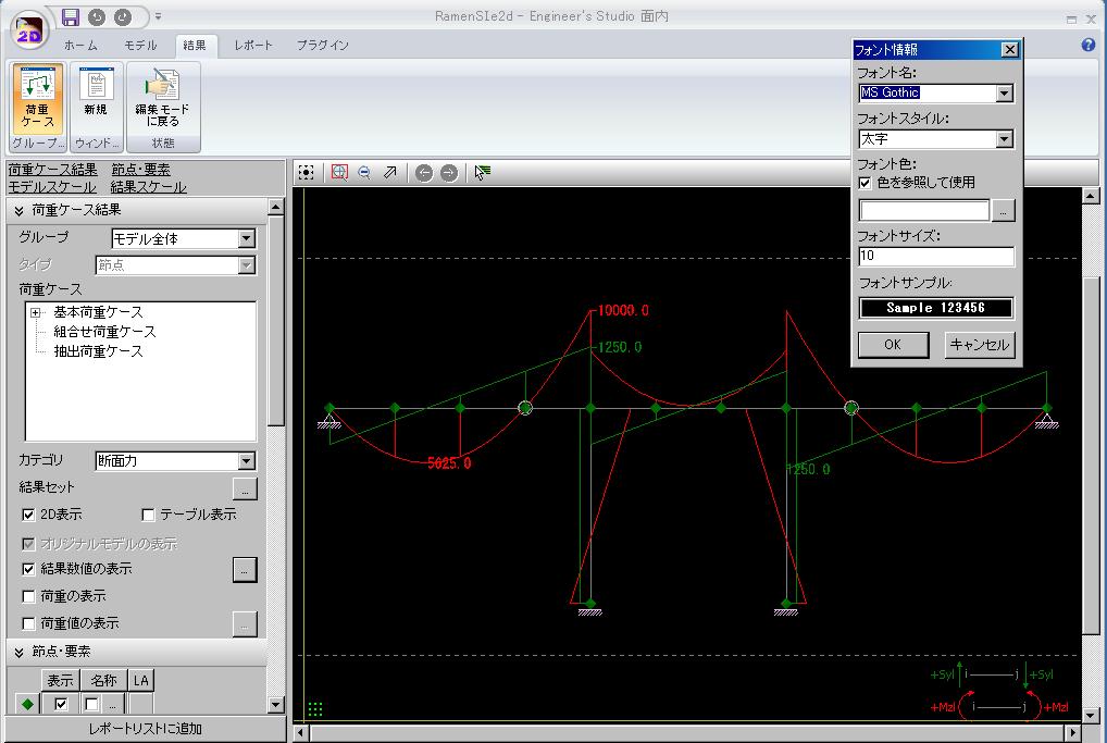
▲ Displacement diagram and section force diagram for the ramen bridge model data

▲ Displacement diagram and section force diagram for the ramen bridge model data

▲ Diagram of the data structure for a truss bridge model

▲ Truss bridge model data editing screen (2 screens)
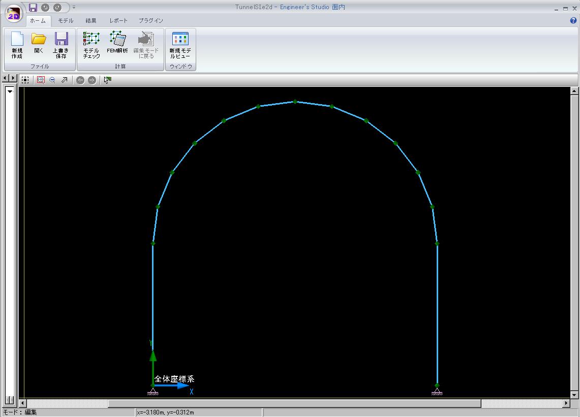
▲ Diagram of the tunnel model data structure
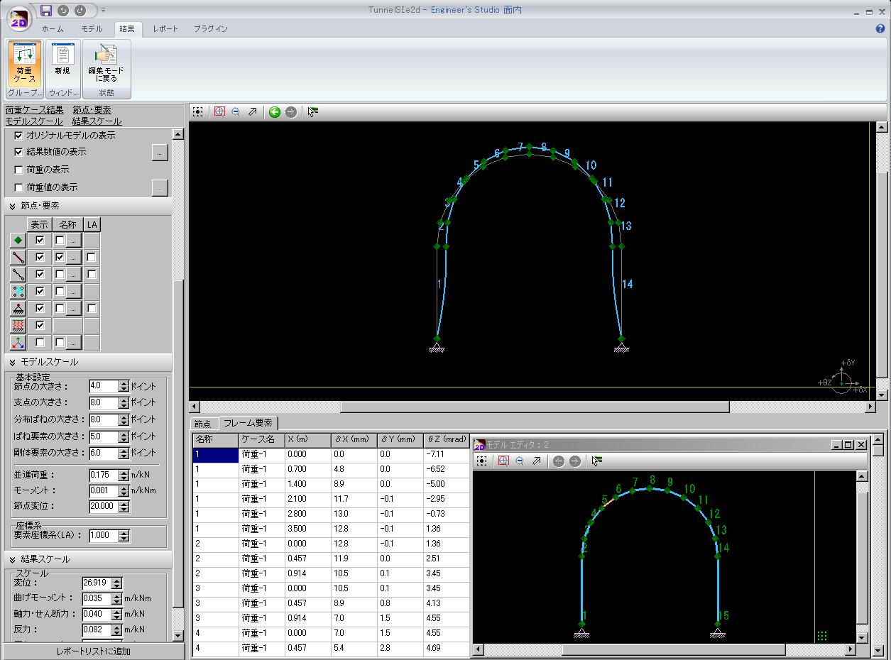
▲ Tunnel model data structure diagram + displacement diagram
PDF Output Example (Insert a 3D model that supports 3D PDF)
▼Arch bridge model data ( 20P, 219KB )  |
▼BOX culvert model data ( 18P, 205KB )  |
▼Pipe model data ( 18P, 176KB )  |
|
▼2-layer ramen model data ( 23P, 272KB )  |
▼Ramen bridge model data ( 20P, 218KB )  |
▼Truss bridge model data ( 22P, 231KB )  |
|
▼Tunnel model data ( 17P, 222KB )  |
|||
Page Top  |
|||

