| 3D real time VR software |
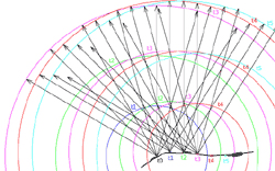
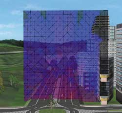
This is the latest plug-in option for UC-win/Road that simulates noise production. It calculates the sound pressure level at a desired location by locating the sound source and sorting the data while considering the surrounding environment. This action can be performed at any point in the screen of UC-win/Road.
Before the noise analysis, you can place the model corresponding to the position of sound source and the defined sound receiving point in UC-win/Road . Accordingly, this function does the following process.
- Acquires the coordinates of the point on the surface of terrain or buildings of UC-win/Road
- Acquires the coordinates and sound characteristics from the sound source data indicated by UC-win/Road.
- Generates the coordinates of the sound receiving point according to the instructions set by UC-win/Road
Enter the followings in the dialog box.
- Parameters:ઠt, and the number of sound radiation path
- Source position:Coordinates of the position, the characteristics of ID, start time of the application , end time of the application
- Sound source characteristics:Fundamental frequency, fundamental ID the frequency
- Fundamental wave: Frequency, initial phase, amplitude
- Sound receiving point:Coordinates of the position, ID of the plane where the point is located
UC-win/Road automatically reads data from the data below.
- Surface of terrain
- Surface of the highway earthwork and pavement
- General model
- Road model
The calculations that this option can do are the following.
- To determine the number and order of diffraction, reflection, penetration and attenuation of each radiation path
- Fading of sound pressure level according to the distances between the sound source position and the sound receiving point
- Allowance of frequency weighting characteristics
- To combine the frequency of sound pressure level for each sound receiving point
- To combine the sound pressure level when the sound of multiple paths reach the receiving point
- To calculate equivalent continuous A-weighted sound pressure level (1998 the Environment Agency Notification No. 64)
Outputs the calculation results as shown below.
- Sound pressure level and equivalent continuous A-weighted sound pressure level of each sound receiving point at the final analysis time (in CSV file)
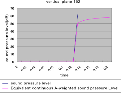
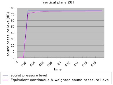
- Sound pressure level for each sound receiving point at all times (for time -sound pressure chart)
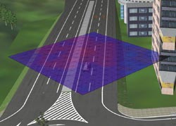
- Sound pressure level for each arbitrary plane at the time of final analysis (UC-win/Road for contour diagram on the screen)
You can display the following charts based on the output data.
- Display the time - sound pressure chart
- Display the contour figure of sound pressure level on UC-win/Road screen
 |
 |
 |
 |
 |
|||
Noise simulation option
(Up & Coming 2009 late fall issue)
