|
|
 |
Case example of system proposal
3D Physical Model&VR System
The scaled model is often used for presentations in various fields including
construction industry, advertisement of heavy equipment, automobile industry.
3D physical model &VR system cover the disadvantages of static scaled
physical model to perform the interactive action between users and models.
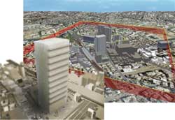
This system consists of three parts (Scaled model of city or part of city,
UC-win/Road, AURELO(AUgmented REality LOcalization))(Figure1). UC-win/Road
is a general-purpose software (3D modeling, simulation, visualization function)which
is used in civil construction industry, automobile industry, etc. AURELO
is a 3D tracking system based on augmented reality(AR) tool, it was originally
designed to arrange the small robot's position on a real-time basis.
We developed it to track the position of laser spot of 3D physical model.
It identifies the change of laser spot, and converts this into the event.
In other words, the laser pointer serves as a function of a standard mouse..
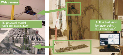 |
| Figure1 Overview of system |
| Performance of 3D model& VR system |
The web camera is positioned at the highest level above the physical model
to capture the entire model (Figure2).
 |
| Figure2 Laser tracking |
The images are acquired and processed by 30 frames per second. AURELO system
continuously reads the position and direction of whole model based on the
position of camera and laser spot and movement (click, double-click). These
data are transmitted to UC-win/Road and the camera view of 3D virtual environment
is updated (Figure3).
 |
| ■Figure3 System operation |
The user interface is very simple, The laser point mouse is used as mouse
to move interactively with 3D virtual environment in a natural flow. Currently
we have developed the trigger of UC-win/Road script when the laser event
is detected in AOI(Area: Area Of Interest). Each AOI is linked with a specific
script according to the user's movement in AOI. We also have processes
to investigate the integration with the dynamic 3D menu of AURELO.
If it is integrated, a wider range of commands will be made available.
In other words, you will be able have direct access from AURELO to the
command of UC-win/Road(Camera position/direction, start/end of scenario,
change of weather).
Case example:"Nakameguro safety and security map" model VR system
Proposal system using Nakameguro area model.
The infrastructure maintenance condition of underground and the inner space
of building can be checked in "Area safety and security map"
which is created by unifying the physical model and VR. It can be used
to facilitate the consensus formation in urban development or redevelopment.
Quotation example
VR data creation:Around 2,700,000Yen
3D model creation:Around 3,500,000Yen
*including other software, hardware, customization development cost, technical
cost
Total 11,600,000 Yen |
 |
|
Case study of 3D Drawing Service
Sample model of distributing reservoir
The below is the sample case study where the distributing reservoir was
modeled using Allplan Engineering which has the strong bar arrangement
tool for RC structure..
In this sample, the distributing reservoir in the underground of water
plant designed in 1969. This distributing reservoir is 19.5m x 23.7m, 5.5m
high, and it is surrounded by walls and twelve columns with footing stand
in a line(Figure1).
 |
| Figure1 Distributing reservoir model |
As for bottomslab and upperslab, the base line with column is called "peristyle
tie" and without column is called "bay tie". The upper edge
bar and lower edge bar are arranged in the combination of Dφ16, Dφ19,
and alternation of Dφ16 and Dφ19 at @125 or @250 in peristyle tie and
bay tie.
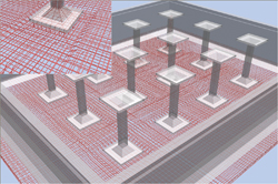
The column part is bending reinforcement, and they are designed for the
lower edge reinforcement to be arranged densely. In the column part, tie
reinforcements of Dφ13 rotate @200. In footing part, the axial reinforcements
spread in all directions around the column(Figure2).
 |
| Figure2:Scale-up column part |
These bar arrangement was performed using the bar arrangement function
of Allplan Engineering.
With Allplan's bar shape tool, the bar diameter and covering thickness
are defined, and stirrup (tie reinforcement) and erection bar are created
by mouse operation. In this sample model, the free form tool is mainly
used. The reinforcement shape is created and they are arranged in the pitch
of @125 or @250. In the column, stirrup (tie reinforcement) tool is used
(Figure3, 4).
 |
|
 |
| Figure3 Bar shape tool |
|
Figure4 Conversion from BIM model
to 2D drawing |
| Advantage of 3D BIM model |
When we created this sample model, we performed the modeling after reviewing
the old drawings written by hand.
The referred hand-writing drawings represented vast amounts of information
simply and efficiently. It is found to be the same between hand-writing
and BIM drawings at the view of the management of information. So what
is the advantage of using BIM The advantage is that anybody can intuitively
understand the conditions of complex bar arrangements by displaying walk
though animation and VR data after converting the drawings from 2D to 3D
instantly in the sample model.
Once 3D models with attribution are created, it will be useful to maintain
the deteriorated concrete and reinforcement and to reinforce them based
on the visualized bar arrangement condition.
In other words, BIM can be used for the maintenance and renovation phase
in future.
In this model, the old distributing reservoir was modeled. Additionally,
the damaged condition can be represented according to the research report.
We also provide the structural analysis with the models created in different
methods.
It is thought that there are many utilization methods by modeling the information.
FORUM8 has launched the 3D and 3D drawing creation service with BIM as
a 3D drawing option of 3D VR engineering service. This service is provided
for architectural and civil engineering constructions. The data will be
submitted to the customers and can be provided by extracting the file output
from the IFC file in Allplan's 3D data.
|
|
|