International Newsletter vol.27 2010/1
1.8.2010 FORUM8 Co., Ltd
--------What's New at FORUM8--------
Seminar reports, new product introduction and user introduction are
on New Year Special Issue of Up and Coming: vol.83
-FORUM 8 Design Festival 2009-3Days report
-User Introduction Vol. 83 Ourston Roundabout Engineering, Inc.
-New Product Introduction: VR StudioTM ver1.1
-New Product Introduction: UC-win/Road for 12d Model
-New Product Introduction: UC-win/FRAME (3D) Ver.4
-Overseas Training and Seminars
Seminar schedule in Shanghai is announced below.
| FORUM 8 Design Festival 2009-3Days | |||||||||||||||||||||
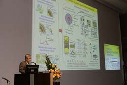
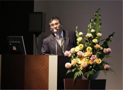
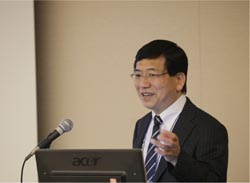
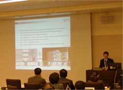
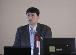
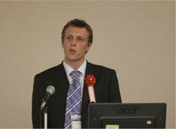
The Design Festival is divided into three events: The Design Conference, which is based around the UC-win/FRAME (3D) User Group, which started in October 2003 after the release of UC-win/FRAME (3D), 3 Dimensional Analysis Program for Space-Framed Structures, in 2002. The User Group has been integrated into Design Conference, combining it with UC-win/UC-1 User Group, and this year marks the 3rd conference. International VR Symposium is held for customers to discuss and utilize the researches, technologies and ideas about Virtual Reality. The symposium started in 2007 as the opportunity to present research activities by World8, an organization of international 3D VR academics from architecture and construction backgrounds. In the year 2009, 3 years after the conception of World8, the number of member doubled. Under the leadership of Yoshihiro Kobayashi, researcher of Prism Laboratory of the Arizona State University and C.E.O. of FORUM8 AZ, the academic group has been carrying out various research activities. At the symposium, various findings from the research activities were presented. "3D VR simulation contest by UC-win/Road" was launched after UC-win/Road won the software product of the year in 2002. This year was the 8th contest and saw various advanced projects both from Japan and abroad. Design Festival 2009 comprised of "Design/Analysis", "Architecture/BIM" and "Water Engineering" sessions on Day 1, "CAD&VR", "Technical" sessions" and "The 3rd International VR Symposium" on Day 2 and "3D VR simulation contest by UC-win/Road" on Day 3. For the convenience of visitors from abroad, we combined our annual events in one festival and had simultaneous interpretation service in 4 languages - Japanese, English, Chinese and Korean. Sessions in the main conference room was broadcast to visitors in our Osaka, Nagoya, Fukuoka and Beijing offices. We are going to report the Design Festival in the New Year Special Issue and the following Early Spring Issue of Up&Coming. |
|||||||||||||||||||||
| <Day1> 3rd Design Conference | |||||||||||||||||||||
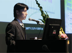
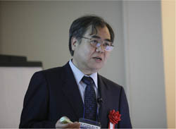
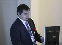
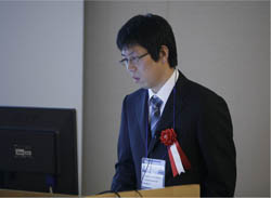
The first session was presented by Brent Fleming, director of FORUM8 director in charge of development, titled "Engineer's Studio(TM) and Future Development". He introduced the overview and new features of Engineers Studio and UC-win/Frame (3D). He also shared the future development plan and presented features in development by showing the operation process. Following the first presentation, next special lecture was by Mr. Hiroki Aoto, Researcher of Tokyo City University, titled "FRAME (3D) Analysis Case and Engineer's Studio's Challenge" Using the case of metal arch bridge, Mr. Aoto talked about utilizing dynamic non-linear analysis by using UC-win/FRAME(3D)'s fiber element for earthquake resistant performance of existing bridges. He also mentioned the request for the future development of Engineer's Studio. >> See report on special lecture2
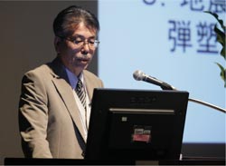
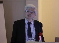
The next presentation was by our analysis support team leader, titled "FRAME (3D) Analysis Case and Analysis Competition Report". Kai introduced the latest analysis case by using UC-win/FRAME(3D) analysis support service of FORUM8. He also introduced the award-winning result from the analysis contest held in "E-defense", the world largest earthquake experiment site, as well as sharing in the methods of modeling. The latter half of the sessions started with the Special Lecture 3 by Mr. Keizo Ugai, Professor of Gunma University Graduate School of Engineering, titled "Ground analysis: Present Situation and Future Development"
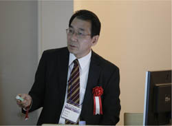
Following Mr. Ugai's session, Mr. Toshihiro Hanada President, Bulld Geotechno Co., Ltd. Gave a special lecture, titled "Ground Analysis Customer Case: Design Overview and Challenge". He introduced case studies of ground analysis by GeoFEAS, such as developed land including cliff for housing complex, deformation of land at the time of repair of pond and earthquake resistance check of existing retaining walls. >> See report on special lecture4
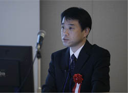
The last lecture of the sessions was "Latest Functions of Ground analysis Series and Slope stability analysis Compliant to New Civil Engineering Construction Guideline" by FORUM8 development manager. He talked about the link between GeoFEAS and VGFlow, ground analysis software, and UC-1 design calculation series. He also explained the overview of the revised Civil Engineering Construction Guideline and Slope Stability Calculation's new features for the latest guideline.
The sessions started with the special lecture by Mr. Ryota Ieiri of Ieiri Laboratory, NikkeiBP , titled "Beyond World Class! Improving BIM of Japanese Spirit with Western Technology" He discussed the positioning of BIM in Japan Build Live Tokyo, overview of BIM, sample cases in other countries, possible innovation by BIM and his expectations about the spread of BIM.
Following Special Lecture 6 was "Allplan(Architecture)Japanese Version" by Mr. Sven Elbl, Director of Product Management of Nemetschek Allplan Gmbh and "Allplan Case Study in Korea -Architecture by Kim Gibom, Basissoft Inc.. Mr. Elbl explained NEMETSCHEK and Allplan software suites, NEMETSCHEK's view on BIM and Allplan's features for BIM. Kim Gibom shared Allplan case studies in Korea and Allplan's functions and customer's merits.
The next presentation was "BIM Solution at Build Live Tokyo" by FORUM8 manager in charge of BIM. He talked about FORUM8's participation in "Build Live Tokyo 2009 2" competition, organized by IAI Japan. He also explained that Allplan and our analysis and simulation products for BIM solution was fully utilized for the Engineering award-winning result at the competition. The latter half of the sessions was started with the Special Lecture 7, "MultiframeVer.12, Plate Element" by Mr. Jake Hannah of Formation Design Systems. Mr. Hannah talked about Multiframe features and its related products. He also discussed plate element, the most significant feature of Multiframe ver.12 and its application to plate models and other plain items and case studies.
These presentations were followed by presentations by technical managers of FORUM8. In the session, titled "Energy Analysis Design Builder Ver.2". Imaizumi talked about the procedures of thermal simulation of buildings and the simulation of CO2 emission by using Design Builder and Energy Plus, building energy simulation software. He also mentioned the possibility of link between Design Builder and FORUM8 solutions. In the session, titled "Exodus, Fire Evacuation Analysis, Example Case and Proposal", Nakamura introduced features and functions of EXODUS, evacuation simulation software, and SMARTFIRE, fire simulation software. He also mentioned the application cases of EXODUS including evacuation examination for apartment blocks, evacuation training from high rise towers and examination of evacuation from car fires in tunnels. In the last session, titled "Analysis Functions by UC-win/Road, Noise, Wind Analysis, Lighting simulation", Okaki discussed the features of noise analysis functions, the latest option of UC-win/Road and thinking method of sound propagation and the procedures of preprocess, data input, analysis calculation, output and post process. He also mentioned the development status of the lighting calculation simulation as well as the wind analysis function.
This session is jointly held with xpswmm Customer Meeting , which is organized by SWMM customer association and supported by NPO Water Environment Construction Club, FORUM8 and XP Software with the theme "Flood Seminar: Latest Information on Flood and running water analysis model. After the opening speech by Mr. Yosihisa Kawahara Professor, Hiroshima University Graduate School, Mr. Kawahara gave a presentation, titled "Challenge for Application of Flood Analysis Technology". He discussed analysis by combination of aero laser survey data and non-structural grids, modeling smaller phenomena by interaction of building-fluid body and calculation grid, and presumption method from the amount of running water from rivers.
The next session was by Mr. Ishikawa Takateru, Water Environment Construction Club, titled "Future Utilization of Running Water Analysis Model for Climate Change" . Mr. Ishikawa talked about the running water analysis models, usage and history of 1D analysis models and 1D/2D analysis models. He also talked about new measures for record-breaking heavy rainfalls caused by climate change and the future utilization of the running water analysis model.
The following special lecture was "Modeling of Flood Risk of Urban Rain Water Drainage" by Mr. Masaru Morita, Professor of Shibaura Institute of Technology. Professor Morita discussed the overview of flood risk management, the evaluation model of flood damage, the method of flood risk assessment, and the application of flood risk assessment.
The latter half of the session started with special lectures by 3 lecturers. Mr. Tatsuo Yamada, Assitant Manager of Nihon Suikou Sekkei Co.,Ltd. gave a presentation, titled "Introduction of Commn MP-Common Platform of Water and Material Circulation Analysis" and introduced the object of developing CommonMP and feature and its development and operation policy, foundation of the consortium, merit and the road map of development.
Mr. Shigenori Kawasaki, Technical Manager, Nihon Suikou Sekkei Co.,Ltd. gave a presentation, titled "Measures to Flooding by Running Water Analysis" and discussed the measures to lower the risk of flooding for flood suffering housing area.
Mr. Kiyotaka Naganawa, Assitant Manager, Nakanihon Engineering Consultants gave a presentation titled, "Analysis of Rivers and Water Channels in an Area by xpswmm". Mr. Kiyotaka Naganawa clarified flooding mechanism and measures by analyzing tunnel covered rivers and water channels in low land area by xpswmm.
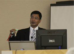
Mr. Ashis Dey Principal of XP-software Pty Ltd. gave a presentation, titled "xpswmm2009, Latest Trend of Flood Analysis Software and Overseas Case Study". He shared basics of hydrology and hydraulics and the functions and possibility of xpswmm. He also introduced the analysis case of 1D/2D integrated modeling.
The last presentation of the sessions was by FORUM8 technical manager, titled "3 Dimensional VR of Flood Analysis: xpswmm Collaborative Functions by UC-win/Road" He introduced the functions and case study of UC-win/Road for xpswmm plug-in option and development schedule of UC-1 series water engineering software. He also shared information about guideline of water supply facility and its revision. |
Day 2 report will be on the next issue of Up and Coming: Up and Coming 84, Early Spring Issue.
"Design, CAD and VR Sessions", "Technical Support Sessions" and
"3rd International VR Symposium" will be featured.
Ourston Roundabout Engineering, Inc. http:://www.ourston.com/ |
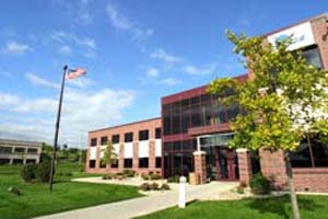
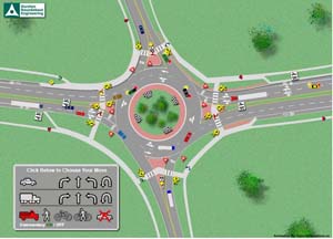
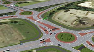
North America's Leading Roundabout Design Team, Ourston has made efforts in Illustrating and Spreading Them: Explaining Mechanisms and Advantages of Roundabout Intersections as an Effective Solution, by Modeling them Using VR |
| A "roundabout" is a form of circular road
intersection at which a vehicle slows down its speed to yield on entry and
enters a one-way path around a central island. Improving conventional circular
junction types, which are called "rotaries", roundabouts have come into wide use
especially in America and Europe, including the U.K. and France, because of
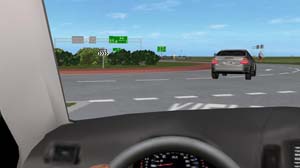
their advantages of high level of safety and efficiency. This issue picks up Ourston Roundabout Engineering Inc., one of the leading roundabout design teams in North America. Its subsidiary company Ourston Traffic Solutions, Inc. specializes in traffic modeling, providing state-of-the-art software solutions. As a part of this, Ourston Traffic Solutions adopted the license of UC-win/Road, 3D real-time VR (virtual reality) software of FORUM8. In early autumn in 2009, the Company became a FORUM8 Premier Partner in North America. In recent years, advantages of modern roundabouts have been recognized in the United States, too. However, there seems to be confusion with the older types of circular intersections such as "rotaries" or "traffic circles". Thus, it was required to get appropriate understanding of the parties concerned by explaining in advance the structure and uses of a roundabout design depending on its individual location as well as its effects and benefits. In searching for the way to satisfy such needs more effectively, Ourston Roundabout Engineering Inc. introduced UC-win/Road in early summer in 2009. On November 20, Ourston Roundabout Engineering Inc. took part in the 8th "3D VR Simulation Contest" sponsored by FORUM8 and held in Tokyo. Ms. Amanda Stubbe, Design Engineer of the Company visited Japan to make a presentation at the contest. As she uses the software as a tool, we asked her to talk from her point of view. In addition, Mr. Mark Lenters, President of the Company, answered our questions by e-mail to complement the interview.
|
|
| New Product Introduction |
|||||||||||||||||
|
|||||||||||||||||
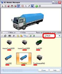
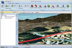
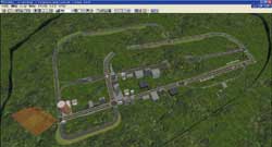
Following the release of the VR Studio(TM) ver1.0, FORUM 8 is set to release VR StudioTM ver1.1, which has improved features from the previous version. This version has revisions including the data creation function and improved performance. Major revisions are as follows.
|
|
||||||||||||||||||
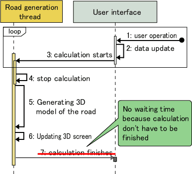
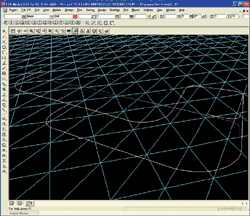
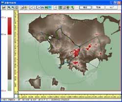
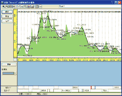
UC-win/Road for 12d Model is the new plug in tool for the data link between UC-win/Road 12d Model. 12d Model offers a total civil engineering solution including surveying. FORUM 8 has developed the plug in, thinking that the bilateral linkage of these 2 software packages contributes to our customers' improved efficiency. The data file is basically based on “12d Ascii File Format", which is a text file, easy to read and its data can be output easily by a string. For details see the following URL. http://www.12d.com/downloads/12d_ascii_file_format.pdf (1) Data link from UC-win/Road to 12d Model
(2) Data link from 12d Model to UC-win/Road
|
||||||||||||||||||
|
||||||||
| Preface Followings are the revised points of UC-win/FRAME(3D) Ver.4.00.00
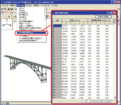
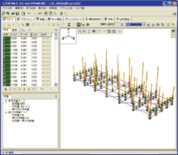
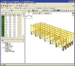
The method required creation of rigid body element and customers had to open edit screen of rigid body element every time you need to define mass points. Spread sheet style input reduces this bothering work. You don't have to generate rigid body element for mass points any more. Giving mass points by spread sheet style enables the value to be reflected to dead load and horizontal seismic coefficient, which are calculated by the program automatically. If you select concentrated mass on setting screen, dead load and horizontal seismic coefficient are reflected to concentrated load to the joints. (diagram 2,3) If you select consistent mass, it is loaded as distributed load to members.(diagram 2,4)
For wider analysis needs These revisions are reflecting request from a lot of customers. Since important functions of analysis will be added in this version, we expect more and more customers can use UC-win/FRAME (3D) for analysis which could not be solved by the previous version. |
||||||||
| To see the full report, visit UC-win/FRAME (3D) Ver.4 on
Up and Coming 83. |
| Overseas
Training and Seminars |
Seminars in Shanghai will be held on the following schedule.
Venue:
Shanghai - Shanghai Seminar room (FORUM8 Technology Development(Shanghai) Co., Ltd)
| Seminar | Date | City |
| UC-win/Road VR | March 3, 2010 | Shanghai |
| UC-win/Road SDK | February 24, 2010 | Shanghai |
| EXODUS/SMARTFIRE | January 27, 2010 | Shanghai |
| Engineer's
Studio, UC-win/FRAME (3D) |
March 17, 2010 | Shanghai |
| xpswmm | January 13, 2010 | Shanghai |
| Maxsurf | March 5, 2010 | Shanghai |
| OSCADY/TRANSYT | March 10, 2010 | Shanghai |
| Multiframe | March 12, 2010 | Shanghai |
| Design Builder | March 24, 2010 | Shanghai |
| Retaining wall design/Temporary sheathing work design Chinese | January 20, 2010 | Shanghai |
| Summary | ||
| Participation Fee | Free | |
For more information and
applications, please email us at
Gross circulation:
When you send a request to unsubscribe from our mailing list, please include "Unsubscribe"
in the subject title of your email and send it back to us.
Thank you for your continued support.
FORUM8 Co., Ltd. mailto:forum8@forum8.co.jp
2-1-1 Nakamegruro GT Tower 15F
Kamimeguro Meguro-ku Tokyo 153-0051 JAPAN
TEL +81-3-5773-1888
FAX +81-3-5720-5688
http://www.forum8.com
